Manual, Signal and Control Module, SA2 SA3
Document #9620-20-C-SA2 SA3-04
Pinnacle Park • 1031 Goodworth Drive • Apex, NC 27539 • Tel: 919.772.0115 • Fax: 919.772.8259 • www.ati-ia.com • Email: info@ati-ia.com
C-15
5. Troubleshooting and Service Procedures
This troubleshooting section provides information to help diagnose conditions with the Tool Changer or control module.
DANGER: This module has a voltage of 50 V or greater; NO contact should be attempted
before removing power. This especially includes separation or insertion of the mating
connectors or any contact with the Tool Changer, Utility Coupler, or its components. Arcing
and damage will occur if this is not observed. Remove power before attaching, disconnecting
any cables or attempting any maintenance of Tool Changer or Utility Coupler.
WARNING: Do not perform maintenance or repair on Tool Changer or modules unless the
Tool is safely supported or placed in the tool stand, all energized circuits (e.g. electrical,
air, water, etc.) are turned off, pressurized connections purged and power discharged from
circuits in accordance with the customer’s safety practices and policies. Injury or equipment
damage can occur with Tool not placed and energized circuits on. Place the Tool safely in the
tool stand, turn off and discharge all energized circuits, purge all pressurized connections,
verify all energized circuits are de-energized before performing maintenance or repair on Tool
Changer or modules.
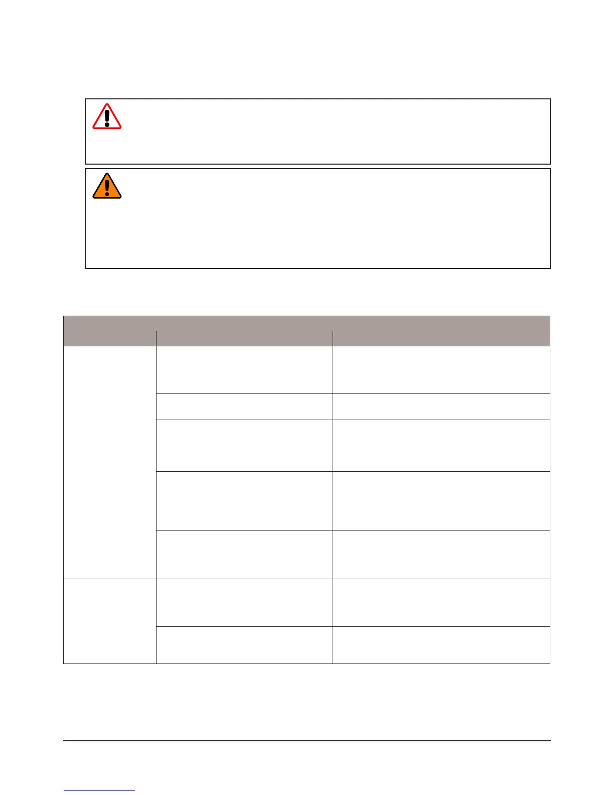
5.1 Troubleshooting
Refer to the table below for troubleshooting information.
Table 5.1—Troubleshooting Procedures
Symptom Possible Cause Correction
Unit will not lock or
unlock
Verify that ball bearings are moving
freely. Clean and lubricate as needed.
Verify that ball bearings are moving freely.
Clean and lubricate as needed. Refer to the
Maintenance section of the Tool Changer manual
for instructions.
Air supply not to specications.
Check air supply. Refer to the Installation section
of the Tool Changer manual for specications.
Check that exhaust port is properly
vented.
Check that exhaust port is properly vented. Refer
to Pneumatic Connection section of the Base
Tool Changer Manual for valve requirements.
Master and Tool are within the specied
No-Touch zone.
Verify that the Master and Tool are within the
specied No-Touch zone when attempting
to lock. Refer to the Installation – Tool Stand
Design Section of the Tool Change manual for
specications.
Air trapped in the Unlock (U) air port.
Ensure that there is no air trapped in the
Unlock (U) air port. Refer to the Air and Valve
adapter section for pneumatic specication and
requirements.
Sensors not
operating properly
Sensor cables damage or incorrectly
connected.
Verify that cables are connected correctly and
not damaged, replace if damaged. Refer to the
Troubleshooting Section of the Tool Change
manual.
Tool plate is not secured properly or
debris is trapped between surfaces.
Ensure that the Tool plate is securely held to the
Master plate, that nothing is trapped between
their surfaces.