Manual, Air Adapters
Document #9620-20-C-Jxx Air Adapters-02
Pinnacle Park • 1031 Goodworth Drive • Apex, NC 27539 • Tel: 919.772.0115 • Fax: 919.772.8259 • www.ati-ia.com • Email: info@ati-ia.com
C-5
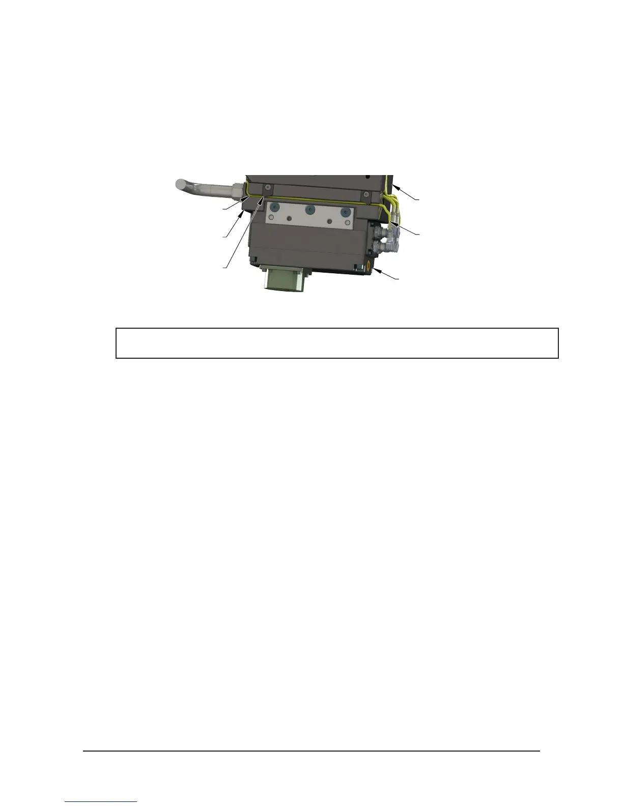
7. Route the RTL (R1) sensor cable through the cable channel in the bottom of the air adapter. Refer to
Figure 2.2.
8. Install the (2) M3 socket at head screws and the (2) cable retaining tabs from the bottom of the air
adapter to secure the RTL (R1) cable. Tighten to 24 in-oz.
9. Make pneumatic connections to the air adapter housing as required. Ensure that the connectors are
cleaned prior to being secured as appropriate. ATI recommends using a thread sealant such as Loctite
569 or similar.
Figure 2.2—RTL (R1) Sensor Cable Routing
Air Adapter
9121-JA2-M (Shown)
Control/Signal Module
Tool Changer Master
(QC-210 Shown)
RTL (R1)
Sensor Cable
(2) Cable Retaining Tabs
Cable Channel in
Bottom of Air Adapter
2.2 Air Adapter Removal for QC-113, QC-210, QC-213, GL6L, GL7L0
NOTICE: Depending on maintenance or repair being performed, utilities to modules and Master
plate may need to be disconnected.
Tools required: 5 mm Allen wrench (hex key), 4 mm Allen wrench (hex key)
1. If the Tool Changer is already installed, dock the Tool side of the Tool Changer safely in the tool stand
and uncouple the Tool Changer to allow clear access to the Master and Tool plates of the Tool Changer.
2. Turn off and de-energize all energized circuits (e.g. electrical, air, water, etc.).
3. Remove the control/signal module off the air adapter. Refer to the control /signal module manual for
instructions.
4. Remove the (2) M3 socket at head cap screws and the (2) cable retaining tabs from the bottom of the
air adapter.
5. Remove the RTL (R1) sensor cable from the cable channel in the bottom of the air adapter.
6. Remove the (2) M5 socket head cap screws and the (2) M6 socket head cap screws and lift the air
adapter off the Tool Changer.
7. Make sure that the O-rings are retained at the Master side Flat ‘A’ mounting interface.