Manual, Signal and Control Module, SA2 SA3
Document #9620-20-C-SA2 SA3-04
Pinnacle Park • 1031 Goodworth Drive • Apex, NC 27539 • Tel: 919.772.0115 • Fax: 919.772.8259 • www.ati-ia.com • Email: info@ati-ia.com
C-3
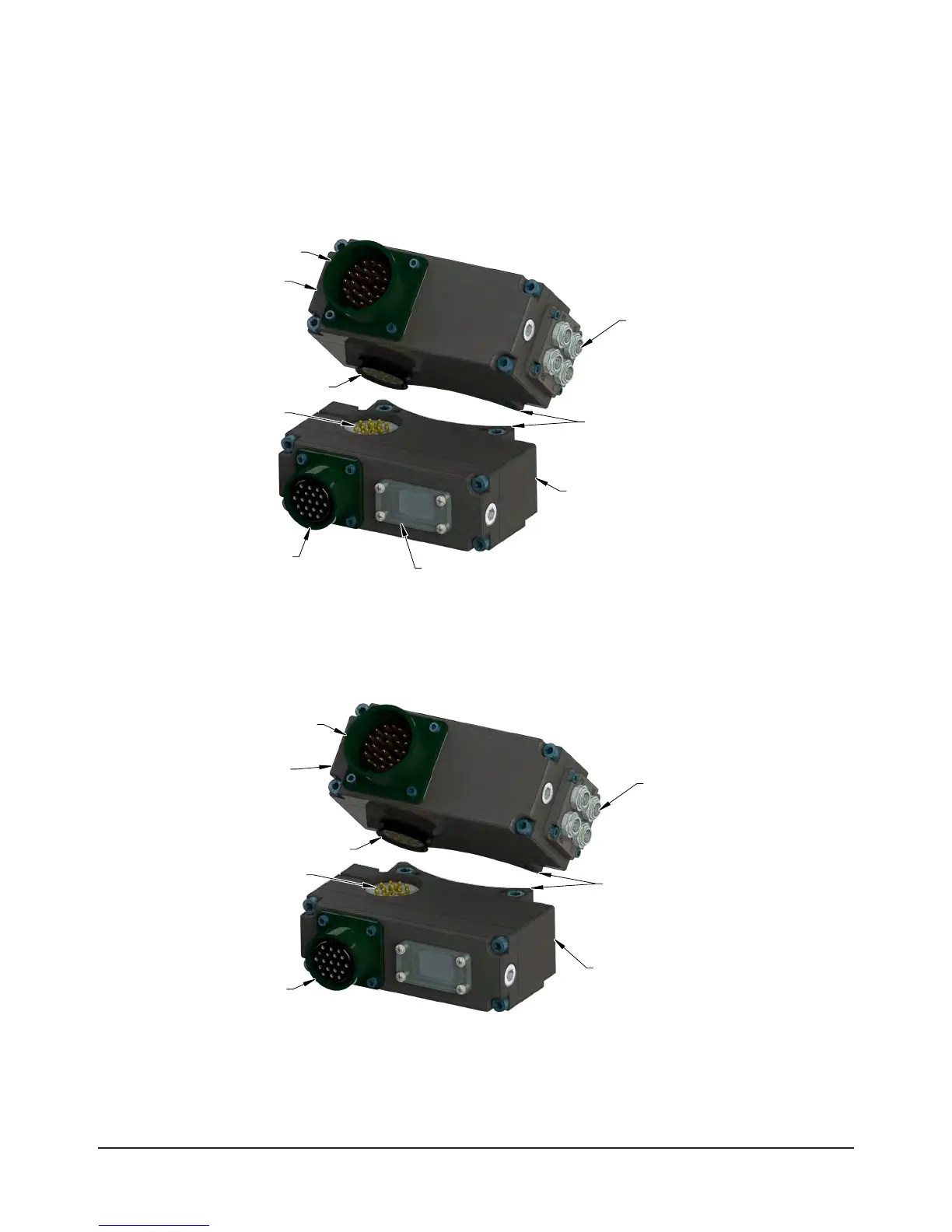
1.1 SA2 Master
The SA2 Master module provides up to 19 pass-through signals. The Master module uses (4) M8 3-pin Pico
connectors to connect to the Lock, Unlock, and RTL sensors on the Tool Changer. The customer interface
connection is an Amphenol 28-Pin MS-style connector. The SA2 Master is compatible with the SA2, SA3,
SA4, SA5, SA6, and SA7 Tool modules.
Figure 1.1—SA2 Modules
Amphenol 28-Pin MS-style
Male Connector
Amphenol 19-Pin MS-style
Female Connector
Common Ledge Mounting Feature
(4) Lock, Unlock, and RTL
Sensor Interface Connectors
M8, 3-pin, Female
Pin Contacts
Spring Pin Contacts
and Rubber V-ring Seal
Tool-ID Switch Location
(Accessible under Window)
Tool Modules:
SA2, SA3, SA4, SA5, SA6, SA7
SA2 Master Module
1.2 SA3 Master
The SA3 Master module is identical to the SA2 Master except that it is potted. The SA3 Master is
compatible with the potted SA6 Tool module.
Figure 1.2—SA3 Modules
Amphenol 28-Pin MS-style
Male Connector
Amphenol 19-Pin MS-style
Female Connector
Common Ledge Mounting Feature
(4) Lock, Unlock, and RTL
Sensor Interface Connectors
M8, 3-pin, Female
Pin Contacts
Spring Pin Contacts
and Rubber V-ring Seal
Tool Module (Potted)
SA6
SA3 Master Module
(Potted)