Manual, Air Adapters
Document #9620-20-C-Jxx Air Adapters-02
Pinnacle Park • 1031 Goodworth Drive • Apex, NC 27539 • Tel: 919.772.0115 • Fax: 919.772.8259 • www.ati-ia.com • Email: info@ati-ia.com
C-4
2. Installation
Air adapters and tool adapter assemblies are typically installed by ATI prior to shipment. The steps below outline
the eld installation or removal as required.
WARNING: Do not perform maintenance or repair on Tool Changer or modules unless
the Tool is safely supported or docked in the tool stand, all energized circuits (e.g.
electrical, air, water, etc.) are turned off, pressurized connections purged and power
discharged from circuits in accordance with the customer’s safety practices and
policies. Injury or equipment damage can occur with Tool not docked and energized
circuits on. Dock the Tool safely in the tool stand, turn off and discharge all energized
circuits, purge all pressurized connections, verify all energized circuits are de-energized
before performing maintenance or repair on Tool Changer or modules.
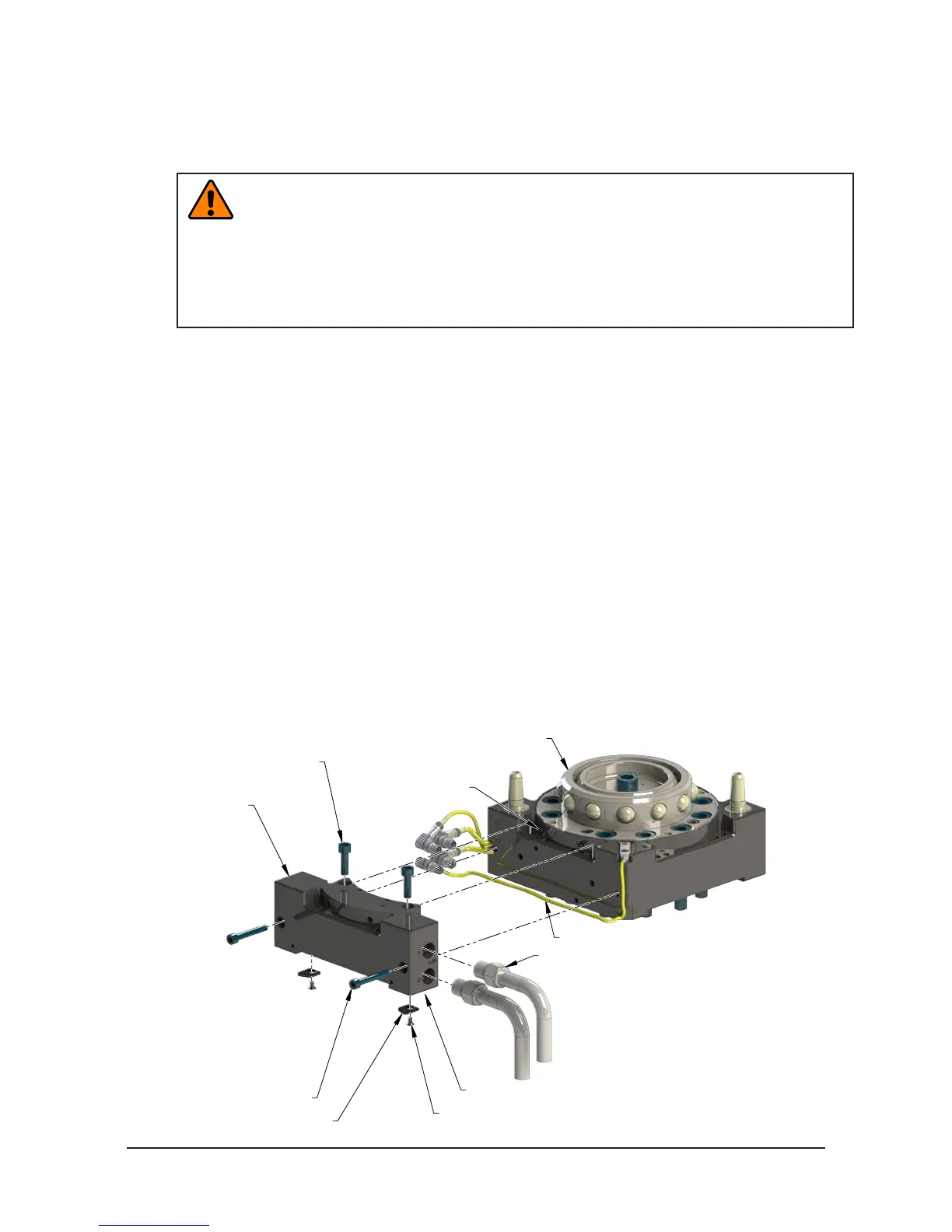
2.1 Air Adapter Installation for QC-113, QC-210, QC-213, GL6L, GL7L
Tools required: 5 mm Allen wrench (hex key), , 4 mm Allen wrench (hex key), torque wrench
Supplies required: clean rag
1. If the Tool Changer is already installed, dock the Tool side of the Tool Changer safely in the tool stand
and uncouple the Tool Changer to allow clear access to the Master and Tool plates of the Tool Changer.
2. Turn off and de-energize all energized circuits (e.g. electrical, air, water, etc.).
3. It may be necessary to clean the mounting surface on the Tool Changer prior to installing the valve
adapter in order to remove any debris that may be present.
4. (2) O-rings are required on the Master side Flat ‘A’ interface. Make sure these O-rings are present and
lightly lubricated (refer to Figure 2.1).
5. Using the ledge feature as a guide place the air adapter adjacent to the ‘Flat A’ mounting surface. Align
the air adapter using the dowels in the bottom of the ledge feature. Apply Loctite 242 to the supplied M6
socket head cap screws. Secure the air adapter using the M6 socket head cap screws and tighten to 70
in-lbs (7.9 Nm).
6. Apply Loctite 222 to the (2) supplied M5 socket head cap screws. Secure the air adapter using the
fasteners, tighten to 55 in-lbs (6.2 Nm).
Figure 2.1—Air Adapter Installation (QC-210 Shown)
Air Adapter
9121-JA2-M
(2) M6 Socket
Head Cap Screws
(2) M5 Socket
Head Cap Screws
(2) O-rings
Tool Changer Master
(QC-210 Shown)
RTL (R1) Sensor Cable
Pneumatic Connections
(2) Cable Retaining Tabs
(2) M3 Socket Flat Head Cap Screws
Cable Channel in Bottom of Air Adapter Module
(Shown)

 Loading...