Manual, Control and Signal Module, SA2 SA3
Document #9620-20-C-SA2 SA3-04
Pinnacle Park • 1031 Goodworth Drive • Apex, NC 27539 • Tel: 919.772.0115 • Fax: 919.772.8259 • www.ati-ia.com • Email: info@ati-ia.com
C-8
2.4 Tool Module Removal
Refer to Figure2.2 for Tool module removal instructions.
Tools required: 5mmAllenwrench
1. If the Tool Changer is already installed, place the tool safely in the tool stand and uncouple the Tool
Changer to allow clear access to the Master and Tool plates of the Tool Changer.
2. Turn off and de-energize all energized circuits (e.g. electrical, air, water, etc.).
3. Disconnect (e.g. power, signal, auxiliary, etc.) cables from the control/signal module.
4. Support the control/signal module, remove the (2) M6 socket head cap screws using a 5 mm Allen
wrench and lift the module from the valve adapter.
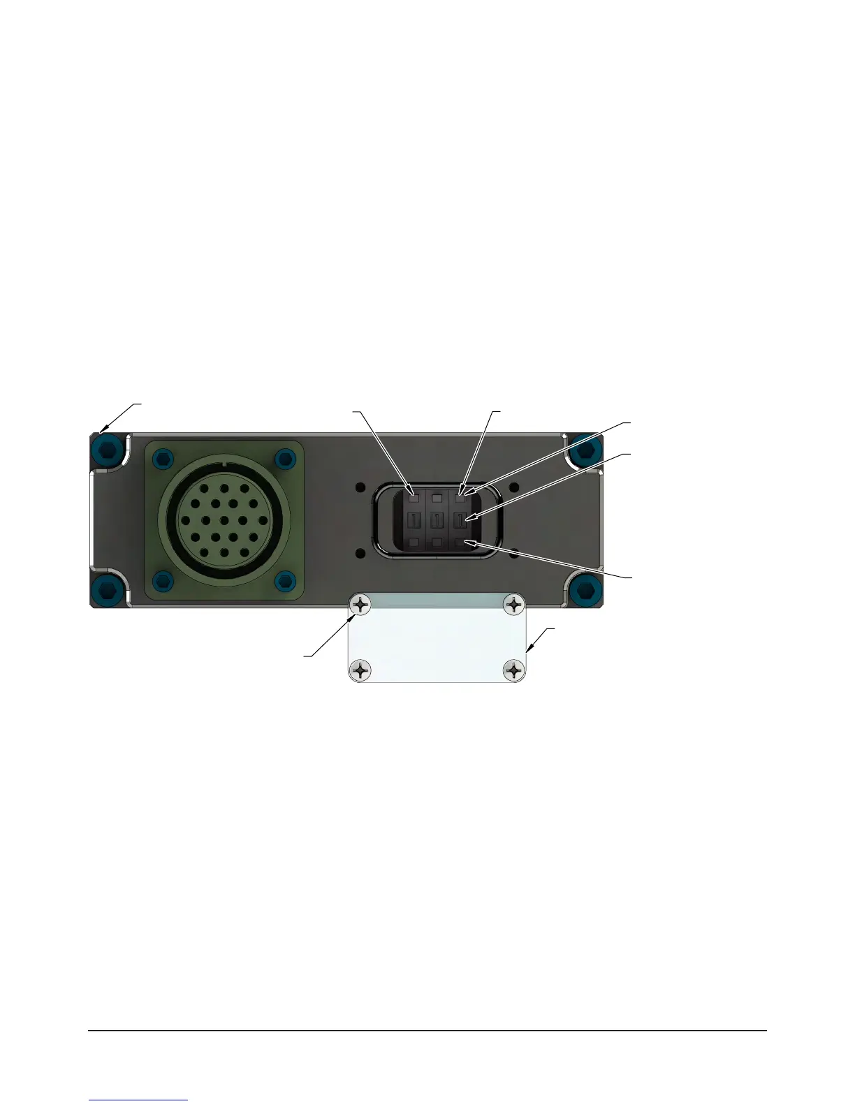
2.5 Setting the Tool-ID on the SA3, SA4, SA5, and SA7 Tool Module
A push button switches are provided on certain Tool modules for setting of a unique digit Tool-ID number.
1. Loosen (4) M3 pan head captive screws and remove Tool-ID window.
Figure 3.1—Set Tool-ID
Decrease (-) Digit
Set Tool-ID to an
unique number
9121-SA3-T:(0-9)
9121-SA4-T: (0-99)
9121-SA5-T: (0-999)
9121-SA7-T: (0-9)
for each tool.
Increase (+) Digit
(4) M3 Pan
Head Captive
Screws
9121-SA5-T Shown
Tool-ID window
SW 1SW 3
2. Use a non-conductive tool (e.g., plastic stylus) to press on the Tool-ID push buttons to increase (+) or
decrease (-) the digit value. Set the Tool-ID to the desired unique digit number. Refer to Section 8—
Drawings for Tool ID output table.
3. Re-install the Tool-ID window and tighten the (4) M3 pan head captive screws.