Manual, Robotic Tool Changer, QC-210
Document #9620-20-B-210 Series Base Tool Changer-26
Pinnacle Park • 1031 Goodworth Drive • Apex, NC 27539 • Tel: 919.772.0115 • Fax: 919.772.8259 • www.ati-ia.com • Email: info@ati-ia.com
B-23
5. Troubleshooting and Service Procedures
The following section provides troubleshooting and service information to help diagnose conditions and repair the
Tool Changer or control/signal module.
WARNING: Do not perform maintenance or repair(s) on the Tool Changer or modules unless
the Tool is safely supported or placed in the tool stand, all energized circuits (e.g. electrical,
air, water, etc.) are turned off, pressurized connections are purged and power is discharged
from the circuits in accordance with the customer’s safety practices and policies. Injury or
equipment damage can occur with the Tool not placed and energized circuits on. Place the
Tool in the tool stand, turn off and discharge all energized circuits, purge all pressurized
connections, and verify all circuits are de-energized before performing maintenance or
repair(s) on the Tool Changer or modules.
5.1 Troubleshooting Procedures
The troubleshooting table is provided to assist in the diagnosing issues that may cause the Tool Changer not
to function properly.
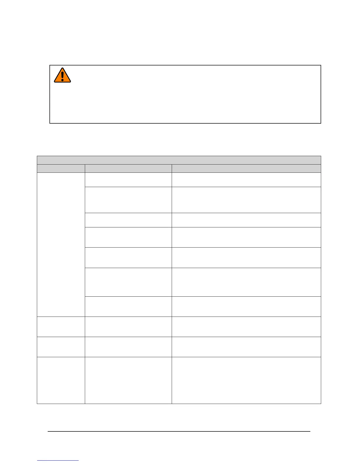
Table 5.1—Troubleshooting
Symptom Cause Resolution
Tool Changer will
not lock and/or
unlock (or Lock
sensor does not
indicate Tool
Changer is Locked)
Insufcient or no air pressure supply
to the lock or unlock ports.
Verify proper air pressure and pneumatic valve is supplied. Refer
to
Section 2.7—Pneumatic Requirements.
Air pressure trapped in the de-
energized Lock or Unlock ports.
Air pressure must be vented to the atmosphere properly,
refer to
Section 2.7—Pneumatic Requirements or refer to the
troubleshooting section of the air/valve adapter manual for more
information.
Pneumatic connections loose or
damaged, solenoid cable damaged.
Refer to the air/valve adapter manual for more information.
Debris caught between the Master
and Tool plates.
Clean debris from the between Master and Tool plates. Verify
mounting fasteners is secure and does not protrude above the
mating surfaces.
The ball bearings and/or cam are not
moving freely in the male coupling.
Clean and lubricate as needed to restore smooth operation (see
Section 4.2—Cleaning and Lubrication of the Locking Mechanism
and Alignment Pins)
The Master plate and Tool plate are
not within the specied No-Touch
zone when attempting to lock.
Check that the Tool is properly seated in the tool stand. Refer to
Section 3.5—Tool Storage Considerations.
Re-teach the robot to bring the Master plate and Tool plate closer
together prior to attempting to lock.
The control/signal module or air/
valve adapter is not operating
correctly.
Check the troubleshooting section of the manual for the specic
module.
Unit is locked but
Lock signal does
not read “on”.
Lock sensor/cable is damaged.
Replace the lock sensor assembly as necessary. Refer to
Section 5.2.1—Sensor Replacement Procedures.
Unit is unlocked but
Unlock signal does
not read “on”
Unlock sensor/cable is damaged.
Replace the unlock sensor assembly as necessary. Refer to
Section 5.2.1—Sensor Replacement Procedures.
Read-To-Lock
(RTL) does not
read “on” when
Master and Tool
plates are mated.
Ready-To-Lock (RTL) sensors
not activated indicating Tool is not
positioned properly.
Re-teach the robot to bring the Master plate and Tool plate
closer together prior to attempting to lock. Refer to
Section 3—
Operation
Check that both RTL sensors and cables are not damaged and
sensor connection to the control/signal module or air adapter
are tight. Replace damaged RTL sensors as necessary. Refer to
Section 5.2.1—Sensor Replacement Procedures.