Manual, Robotic Tool Changer, QC-210
Document #9620-20-B-210 Series Base Tool Changer-26
Pinnacle Park • 1031 Goodworth Drive • Apex, NC 27539 • Tel: 919.772.0115 • Fax: 919.772.8259 • www.ati-ia.com • Email: info@ati-ia.com
B-5
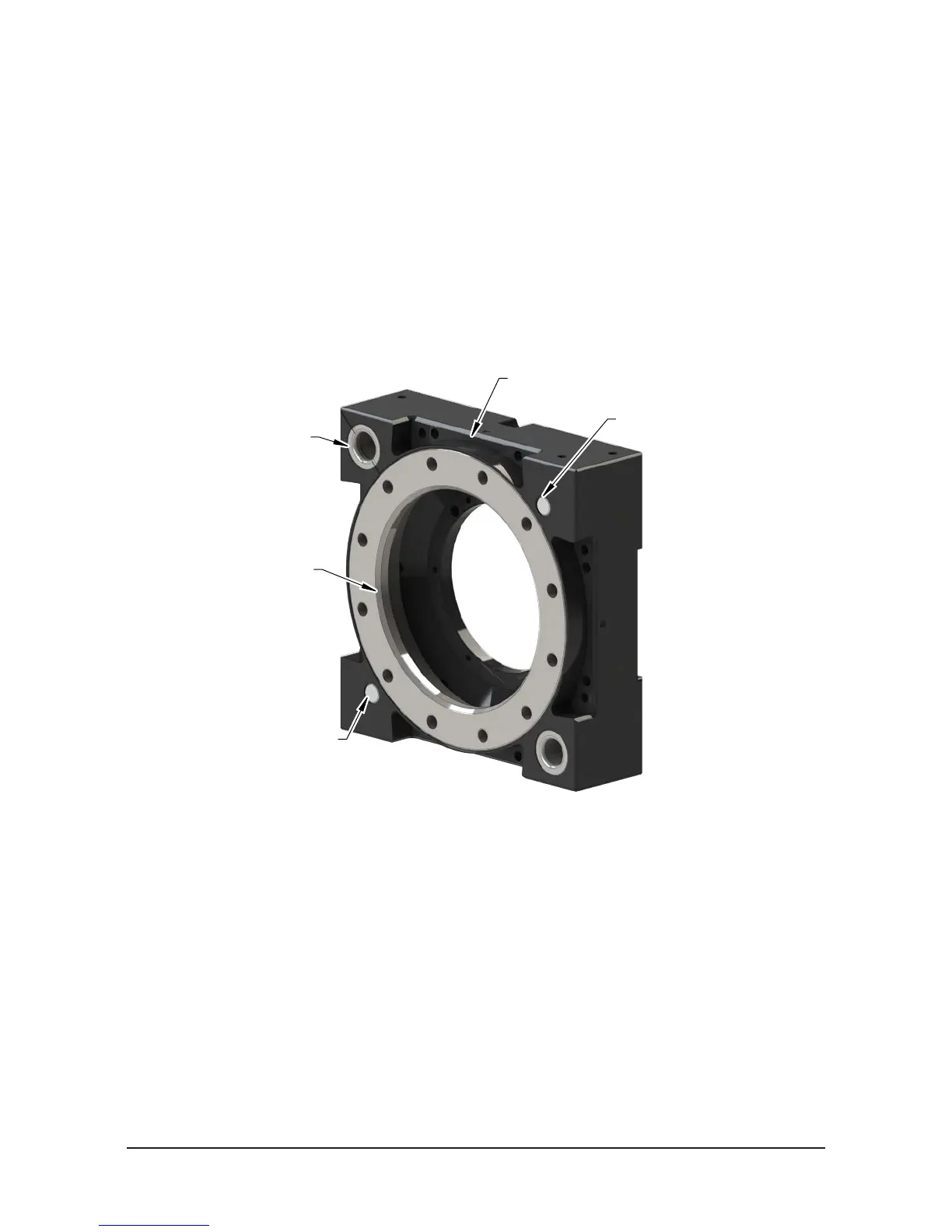
1.2 Tool Plate Assembly
The Tool plate assembly includes the following features:
• An anodized aluminum body.
• A hardened stainless steel bearing race.
• Alignment bushings that mate with pins on the Master plate.
• (4) ats for mounting optional modules. Flat A requires a tool adapter assembly that is compatible with
the air or valve adapter used on the Master Plate. Flats B, C, and D are for optional modules.
• Ferrous metal proximity sensor targets.
• A mounting pattern for customer tooling or a tooling interface plate.
Figure 1.2—Tool Plate Assembly
(2) Alignment Pin
Bushing
Bearing Race
Proximity Sensor
Assembly Target (RTL)
Proximity Sensor
Assembly Target (RTL)
Common Ledge Feature for
Module mounted to Flat A,
B, C, and D
1.3 Optional Modules
The optional modules are mounted to the Master and Tool plate using a common ledge mounting feature and
pass utilities to customer tooling.
For assistance in the choosing the right modules for your particular application, visit our website (http://
www.ati-ia.com/products/toolchanger/QC.aspx?ID=QC-210) to see what is available or contact an ATI sales
representative.