Quick Change Installation and Operation Manual
Document #9620-20-E-ED15-04
Pinnacle Park • 1031 Goodworth Drive • Apex, NC 27539 USA • Tel: 919.772.0115 • Fax: 919.772.8259 • www.ati-ia.com • Email: info@ati-ia.com
E-2
E. Electrical Modules
ED15—Servo Module
1. Product Overview
A servo module may be provided on the Tool Changer to pass electrical power and signal connections to a transgun
servo motor. Refer to Section7—Specications for the details of each module. The connectors on this module
are located such that the tool side power and signal cables can be routed separately. Power and signal circuits are
electrically isolated both from each other and the Tool Changer. The wiring has EMI/RF shielding to protect it from
noise.
DANGER: This module has a voltage of 50 V or greater, NO contact should be attempted
before removing power. This especially includes separation or insertion of the mating
connectors or any contact with the Tool Changer or its components. Arcing and damage will
occur if this is not observed. Remove power before attaching, disconnecting any cables or
attempting any maintenance of Tool Changer.
Compliant spring probes are provided on the Master and xed contact pins on the T
ool. Signal circuits are designed
to be water-resistant but they are not waterproof. On the signal circuit, the central pins are rst-to-mate and last-
to-break during a Tool change. It is recommended that these pins be used as the designated ground. To avoid
unintentional human contact, the Master spring pins are recessed below an insulated surface on both the power and
signal circuits.
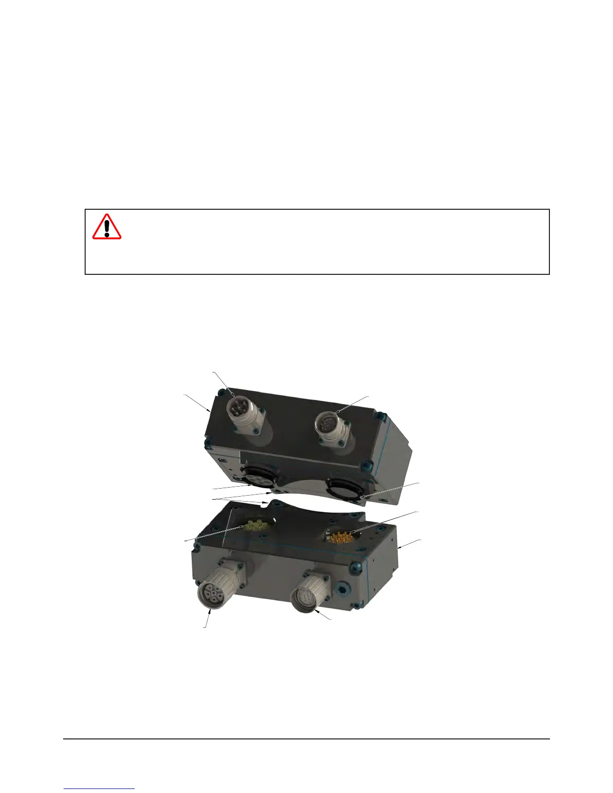
Figure 1.1—ED15 Modules
Signal Connector
Intercontec 12-pin male
Power Connector
Intercontec 6-pin male
9121-ED15-M
9121-ED15-T
Signal Connector
Intercontec 12-pin female
Power Connector
Intercontec 6-pin female
19-pin Signal Contacts
7-pin Spring Power
Contacts and V-ring Seal
7-pin Power Contacts
19-pin Spring Signal
Contacts and V-ring Seal
Common Ledge Mounting Feature
1.1 ED15 Master Module
An Intercontec 6-pin male connector is provided for power and an Intercontec 12-pin male connector is
provided for signals.
1.2 ED15 Master Module
An Intercontec 6-pin female connector is provided for power and an Intercontec 12-pin female connector is
provided for signals.