Manual, Air Adapters
Document #9620-20-C-Jxx Air Adapters-02
Pinnacle Park • 1031 Goodworth Drive • Apex, NC 27539 • Tel: 919.772.0115 • Fax: 919.772.8259 • www.ati-ia.com • Email: info@ati-ia.com
C-6
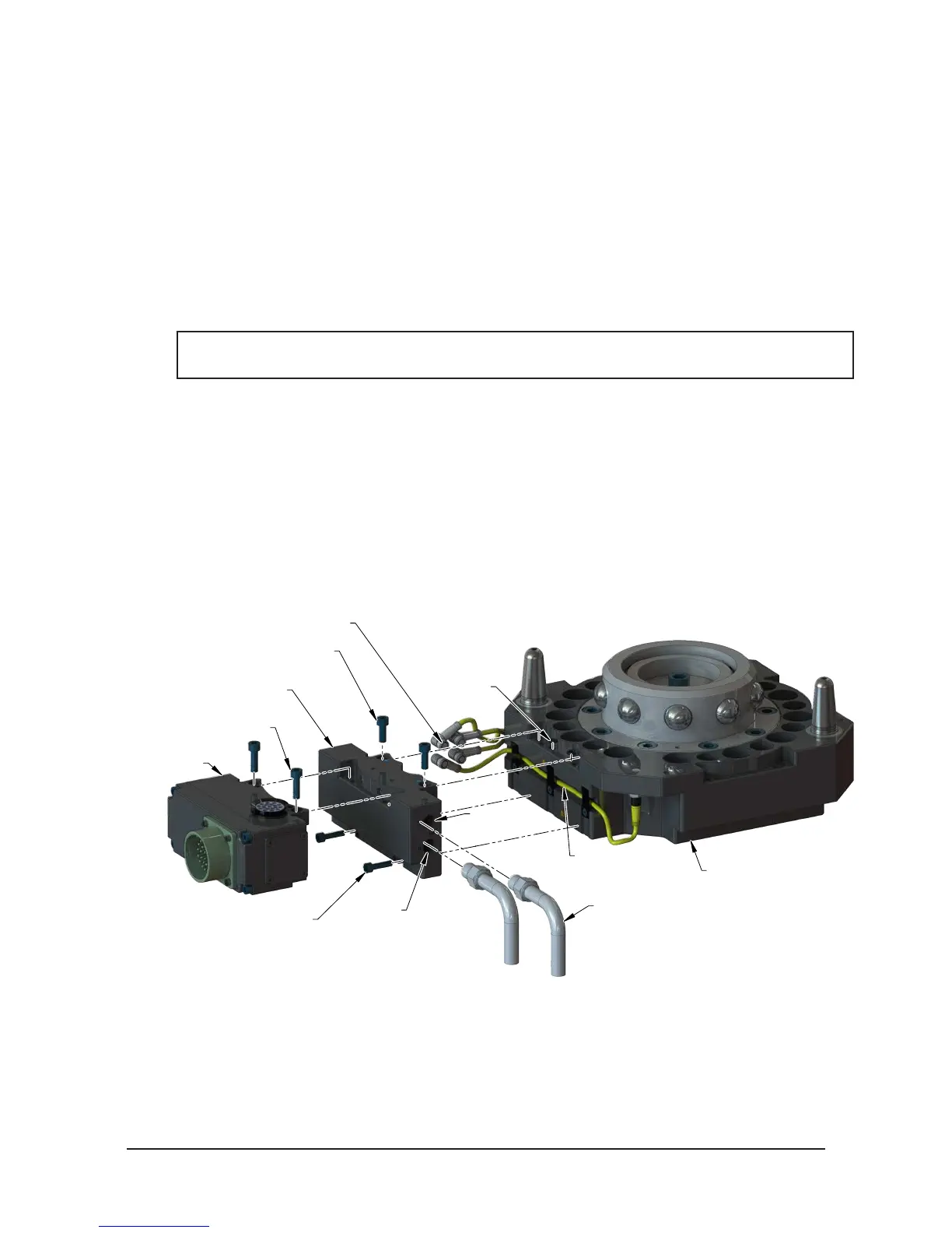
2.3 Air Adapter Installation for QC-310, QC-313, QC-510, QC-1210
Tools required: 5 mm Allen wrench (hex key), 4 mm Allen wrench (hex key), torque wrench
Supplies required: clean rag
1. If the Tool Changer is already installed, dock the Tool side of the Tool Changer safely in the tool stand
and uncouple the Tool Changer to allow clear access to the Master and Tool plates of the Tool Changer.
2. Turn off and de-energize all energized circuits (e.g. electrical, air, water, etc.).
3. It may be necessary to clean the mounting surface on the Tool Changer or Utility Coupler prior to
installing the air adapter in order to remove any debris that may be present.
4. (2) O-rings are required on the Master side Flat ‘A’ interface. Make sure these O-rings are present and
lightly lubricated (refer to Figure 2.3).
NOTICE: Makes sure the RTL (R1) sensor cable is completely in the cable channel in the Tool
Changer body, so it will not get pinched when installing the air adapter.
5. Using the ledge feature to place the air adapter adjacent to the ‘Flat A’ mounting surface. Align the air
adapter using the dowels in the bottom of the ledge feature. Apply Loctite 242 to the supplied M6 socket
head cap screws. Secure the air adapter using the M6 socket head cap screws and tighten to 70 in-lbs (7.9
Nm).
6. Apply Loctite 222 to the (2) supplied M5 socket head cap screws. Secure the air adapter using the
fasteners and tighten the M5 socket head cap screws to 55 in-lbs (6.2 Nm).
7. Make pneumatic connections to the air adapter housing as required. Ensure that the connectors are
cleaned prior to being secured as appropriate. ATI recommends using a thread sealant such as Loctite
569 or similar.
Figure 2.3—Air Adapter Installation (QC-310 Shown)
(2) M6 Socket Head
Cap Screws
(2) M5 Socket
Head Cap Screws
(2) M6 Socket Head Cap Screws
Valve Adapter
9121-JA3-M (Shown)
(2) O-rings
Pneumatic
Connections
Lock
Air Port
Lock, Unlock, and
RTL R1 and R2 Connectors
Control/Signal
Module
RTL (R1)
Sensor Cable
Unlock
Air Port
Tool Changer
(QC-310 Shown)