Manual, Air Adapters
Document #9620-20-C-Jxx Air Adapters-02
Pinnacle Park • 1031 Goodworth Drive • Apex, NC 27539 • Tel: 919.772.0115 • Fax: 919.772.8259 • www.ati-ia.com • Email: info@ati-ia.com
C-8
2.6 Tool Adapter Assembly Removal
NOTICE: Depending on maintenance or repair being performed, utilities to modules may need
to be disconnected.
Tools required: 5 mm Allen wrench (hex key), 4 mm Allen wrench (hex key)
1. If the Tool Changer is already installed, dock the Tool side of the Tool Changer safely in the tool stand
and uncouple the Tool Changer to allow clear access to the Master and Tool plates of the Tool Changer.
2. Turn off and de-energize all energized circuits (e.g. electrical, air, water, etc.).
3. Remove the control/signal module off the tool adapter assembly. Refer to the control /signal module
manual for instructions.
4. Remove the (2) M5 socket head cap screws and the (2) M6 socket head cap screws and lift the tool
adapter assembly off the Tool Changer or Utility Coupler. (refer to Figure 2.4).
2.7 Pneumatic Connections
The air supply used for coupling and uncoupling the Tool Changer should be clean, dry, and non-lubricated.
A supply pressure in the range of 60 to 100 psi is acceptable for operation of the locking mechanism, with a
setting of 80 psi suggested. The air should be ltered 40 micron or better.
CAUTION: Do not use the Tool Changer in a fail-safe condition. Do not transport the
Tool Changer in a fail-safe condition. Possible damage to the locking mechanism could
occur. Re-establish air pressure to Tool Changer before returning to normal operations.
2.7.1 Valve Requirements and Connections for the Locking Mechanism
When an air adapter is utilized that does not contain an integrated solenoid valve, it is required that
a customer supplied 2-position 4-way or 5-way valve be used to actuate the locking mechanism
in the Master plate. It is imperative that when air is supplied to the Lock or Unlock Port on the
Master plate, that the opposite port be vented to atmosphere (i.e., when air is supplied to the Lock
Port, the Unlock Port must be open to the atmosphere.) Failure to vent trapped air or vacuum on the
inactive port may inhibit proper shuttling of the valve and prevent coupling and/or uncoupling from
occurring.
CAUTION: The locking mechanism will not function properly when connected
to a 3-way valve as this type of valve is incapable of venting trapped air
pressure from within the Tool Changer. This could result in damage to the
product, attached tooling, or personnel. Connect the Lock and Unlock supply
air to a 2-position 4-way or 5-way valve.
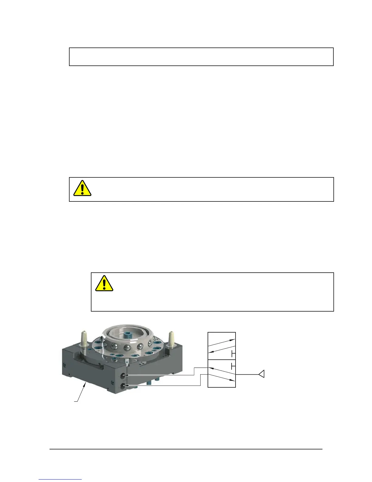
Figure 2.5— Lock and Unlock Pneumatic Connections
4 or 5-way Valve
Supply Clean, Dry,
Non-lubricated Air
60
- 100 psi (4.1 - 6.9 Bar)
Exhaust
Open to Atmosphere
Lock Port
Unlock Port