Quick Change Installation and Operation Manual
Document #9620-20-E-ED15-04
Pinnacle Park • 1031 Goodworth Drive • Apex, NC 27539 USA • Tel: 919.772.0115 • Fax: 919.772.8259 • www.ati-ia.com • Email: info@ati-ia.com
E-3
2. Installation
The servo modules are typically installed by ATI prior to shipment. The steps below outline the eld installation or
removal as required. For wiring information refer to Section8—Drawings.
DANGER: This module has a voltage of 50 V or greater, NO contact should be attempted
before removing power. This especially includes separation or insertion of the mating
connectors or any contact with the Tool Changer or its components. Arcing and damage will
occur if this is not observed. Remove power before attaching, disconnecting any cables or
attempting any maintenance of Tool Changer.
WARNING: Do not perform maintenance or repair on Tool Changer or modules unless the
Tool is safely supported or docked in the tool stand and all energized circuits (e.g., electrical,
air, water, etc.) have been turned off. Injury or equipment damage can occur with Tool not
docked and energized circuits on. Dock the Tool safely in the tool stand and turn off all
energized circuits before performing maintenance or repair on Tool Changer or modules.
2.1 Module Installation
1. If the Tool Changer is already installed, dock the Tool side of the Tool Changer safely in the tool stand
and uncouple the Tool Changer to allow clear access to the Master and Tool plates of the Tool Changer.
2. Turn-off and de-energize all circuits (e.g. electrical, air, water, etc.).
3. It may be necessary to clean the mounting surface on the Tool Changer prior to installing the module in
order to remove any debris that may be present.
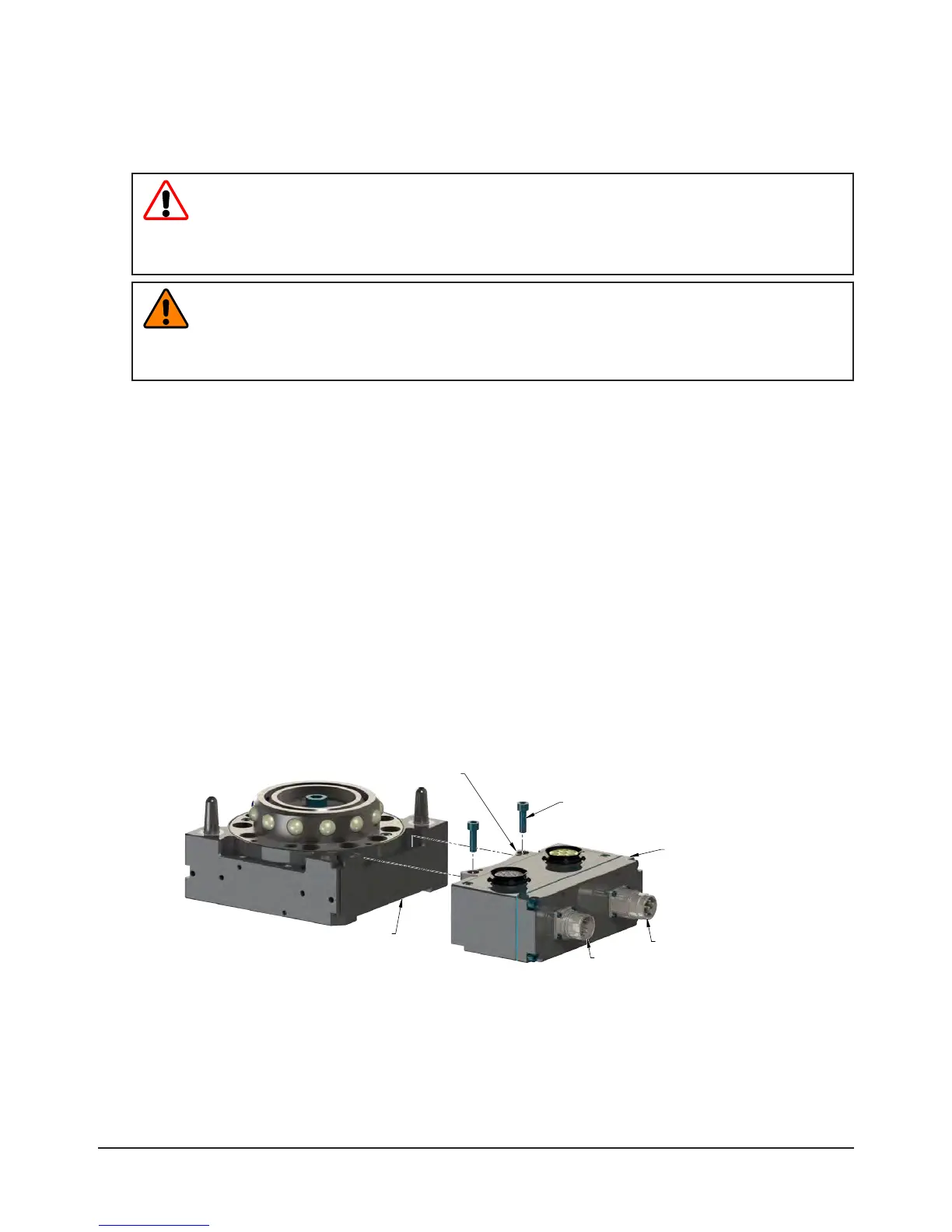
4. Using the ledge feature as a guide place the module into the appropriate location on the Tool Changer
body. Align the module with the Tool Changer using the dowels in the bottom of the ledge feature. Refer
to Figure2.1.
5. If fasteners do not have pre-applied adhesive, apply Loctite 242
®
to the supplied M6 socket head cap
screws fasteners. Install the (2) M6 socket head screws securing the module to the Tool Changer and
tighten to 70 in-lbs (7.9 Nm).
6. Power and signal cables can be connected to the module after attaching the module to the Tool Changer
body. Ensure that the connectors are cleaned prior to being secured as appropriate.
7. If installation is complete, modules may be put into normal operation.
Figure 2.1—Module Installation
Tool Changer
ED15 Servo Module
M6 Socket Head Cap Screws
Feature to Properly Align Module
Power Connector