Manual, Robotic Tool Changer, QC-210
Document #9620-20-B-210 Series Base Tool Changer-26
Pinnacle Park • 1031 Goodworth Drive • Apex, NC 27539 • Tel: 919.772.0115 • Fax: 919.772.8259 • www.ati-ia.com • Email: info@ati-ia.com
B-25
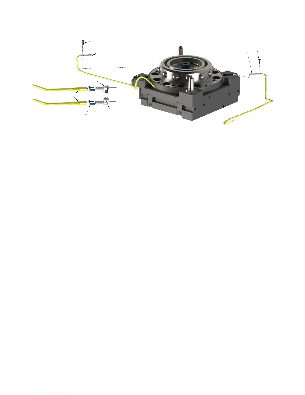
Figure 5.2—Lock and Unlock Sensor Assembly Replacement
M3 Socket Head Cap Screw
Unlock Sensor Assembly
Lock Sensor Assembly
Sensor Cables
M3 Socket Flat Head Cap Screw
RTL Sensor Flat Pack Style RTL Sensor Flat Pack Style
M3 Socket Flat Head Cap Screw
7. Install the new lock and/or unlock sensor assembly, routing the cable into the cable
channel of the Tool Changer body.
8. Attach the sensor cable connectors to the lock and/or unlock sensor.
9. Insert the lock and/or unlock sensor assembly into the Tool Changer body.
10. Apply Loctite 222 to the M3 socket head cap screws. Secure the sensor assembly
with the (2) M3 socket at head screws. Tighten to 12 in-lbs (1.4 Nm) using a
2.5 mm Allen wrench.
11. Conrm the operation of the Unlock sensor by unlocking the Tool Changer and
then checking to see If the Unlock sensor cable LED is on.
12. After the procedure is complete, resume normal operation.
5.2.1.2 RTL Sensor Replacement (ST and SU Sensor Designation)
Refer to Figure 5.2.
Parts required: Refer to Section 6—Serviceable Parts
Tools required: 2 mm Allen wrench (hex key), torque wrench
Supplies required: Loctite 222
1. Place the Tool in a secure location.
2. Uncouple the Master and Tool plates.
3. Turn off and de-energize all energized circuits (e.g. electrical, air, water, etc.).
4. Using a 2 mm Allen wrench, remove the M3 socket at head cap screw that secure
the RTL sensor to the Tool Changer body.
5. Disconnect the RTL sensor cable.
6. Remove the RTL sensor from the Tool Changer body. Discard the removed RTL
sensor.
7. Connect the RTL sensor cable.
8. Install the RTL sensor to the Tool Changer body.
9. Apply Loctite 222 to the M3 socket at head screws. Secure the sensor to the Tool
Changer body and tighten to 60 in-ozs (0.4 Nm) using a 2 mm Allen wrench.
10. After the procedure is complete, resume normal operation.