70 User’s Manual—SNAP™ 500 Gen 1 and Gen 2
Classification: Avery Dennison - Public
WARNING: Knife adjustments procedure must be followed
exactly or damage will occur.
WARNING: When adjusting, removing, or replacing the
knife assembly, you must turn off the power to the printer
to avoid personal injury.
1. Turn off the power to the printer.
2. Remove the knife assembly from the printer as described in Section 4.4.1. Refer
to Figures 18a and 18b.
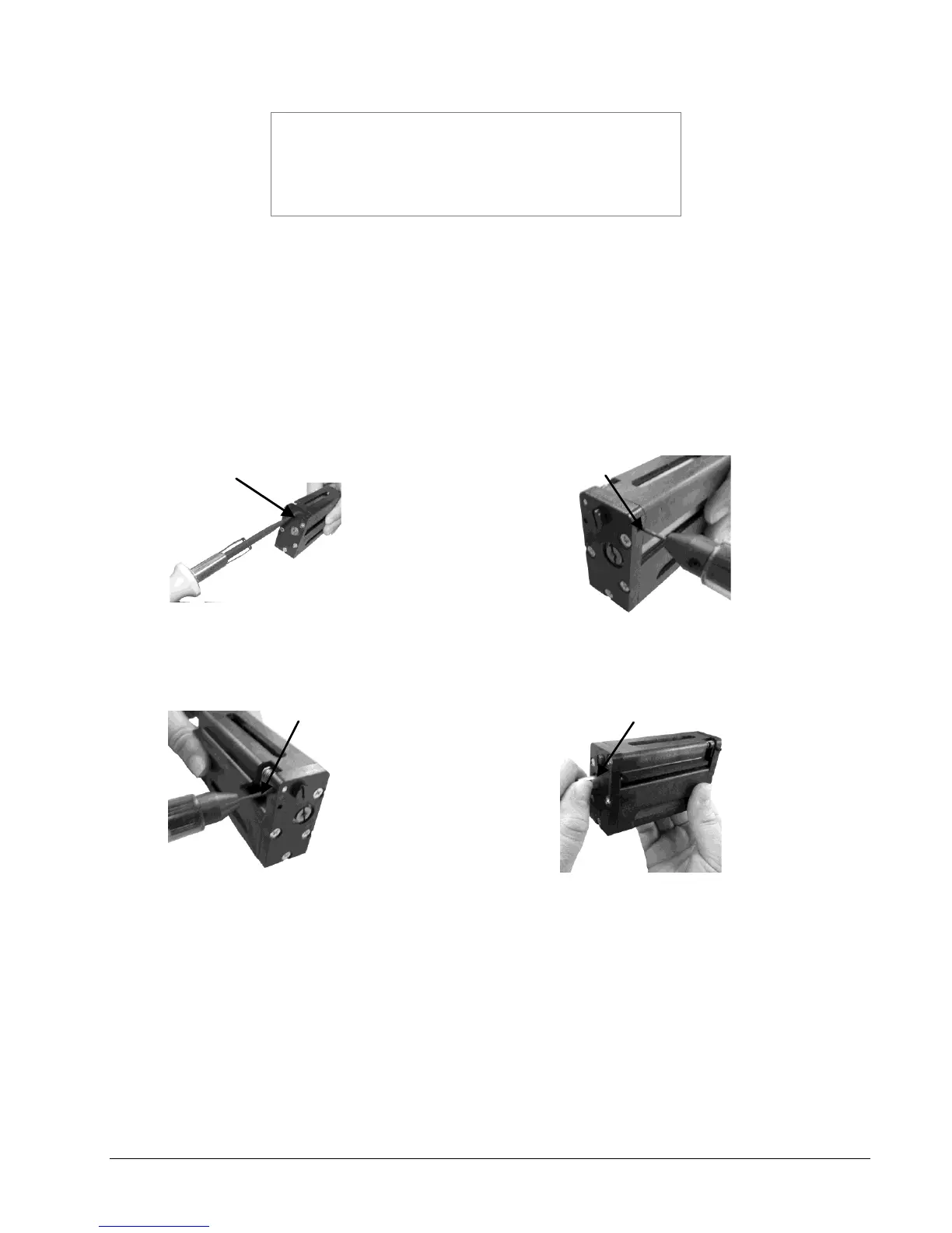
3. Loosen the outer pivot screw by making one complete turn (see Fig. 19a).
4. The two setscrews move the stationary outboard end of the knife to increase or
decrease the shear.
5. To increase the shear, loosen the right setscrew ¼ turn (see Fig. 19b) and
tighten the left setscrew (see Fig. 19c).
Figure 19a. Loosening Outer Pivot Screw Figure 19b. Adjusting Right Set Screw
Figure 19c. Adjusting Left Set Screw Figure 19d. Manual Rotation of Knife Shaft
6. Re-tighten the outer pivot screw. Screw should be snug but not over tightened.
Over tightening may prevent the upper blade from rotating.
7. Rotate the shaft by hand, using the inboard shaft extending from the assembly
(Fig. 19d). The knife should rotate freely, and will make a metallic shearing
sound during rotation.
8. Insert a strip of the material to be cut so it extends from both sides of the knife.
Test by rotating the knife shaft again to cut the material.