CHAPTER 4 – Installation
Chap. 4
- 19/20 -
STEP ACTION DESCRIPTION
4
Levelness
check
• Measure the levelness of the X axis by placing a precision level halfway
along the length of the X axis ball screw or halfway along the length of one
of the X axis linear guides.
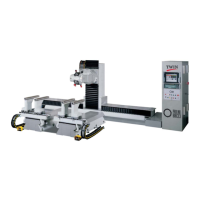
5
Adjustment
• Turn the four adjustment screws (2) at the corners of the machine body.
Turn the screws 1/4 turn at a time.
6
Levelness
check
• Measure the levelness of the Y axis by placing a precision level on the
resting plate.
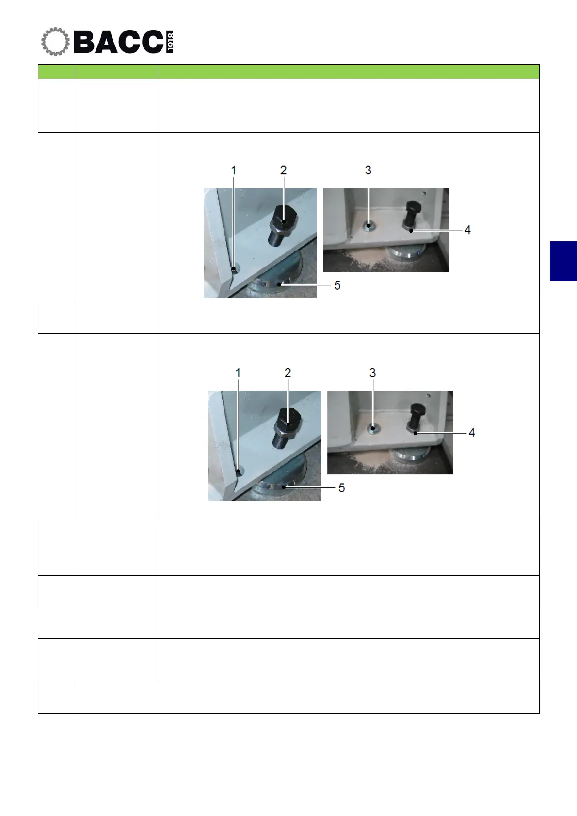
7
Adjustment
• Turn the four adjustment screws (2) at the corners of the machine body.
Turn the screws 1/4 turn at a time.
8
Fastening the
plates
• Act on the adjustment screws (2) to rest all the other plates on the ground
uniformly. Always turn the pair of screws at the opposite ends by 1/4 of a
turn at a time.
9
Leveling
• Check levelness along the X axis and the Y axis.
10
Tightening the
screws
• Block the adjustments screws using the lock-nuts (4).
11
Inserting
anchor screws
• Use the anchoring holes (1) as a template to drill the anchoring holes in the
ground for the anchor screws.
12
Anchoring
• Anchor the machine body to the ground using the anchoring bolts (3).