Chap. 3
- 7/28 -
CHAPTER 3 – Machine description and technical data
3.6 Machine layout
3.6.1 Machine operating diagram
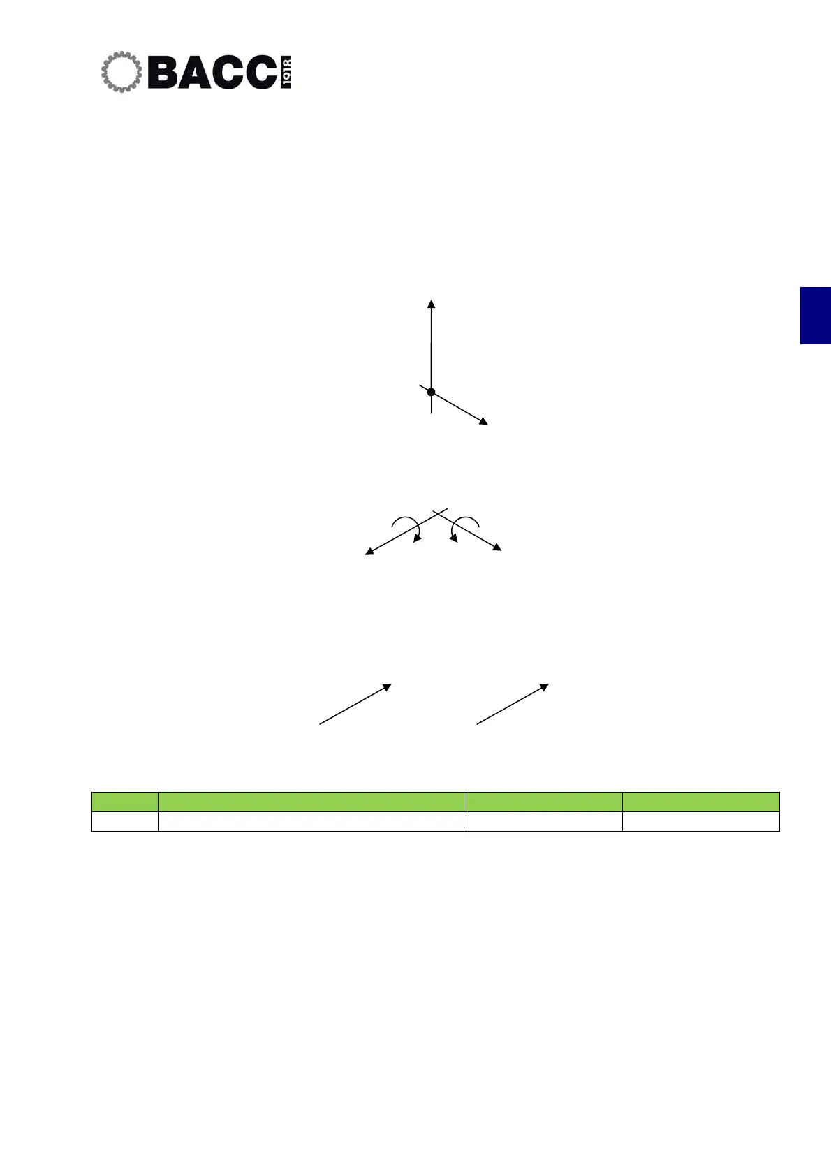
The figure below represents the machine operating diagram: specifically, it represent the axes and relative
movements carried out by the operating units.
STRUT
B-A HEAD
TABLE
HEADS MACHINE BODY PIECE TRADENAME
1
MOVABLE STRUT (X,Z) , HEAD (B,A) TABLE (Y1,Y2) TWIN
The axes controlled by the machine are:
• X axis
• Transversal axes of the Y axis carriage
• Vertical Z axes of the Z axis carriages
• Rotating A axes of the operating heads
• Rotating B axes of the operating heads
Each axis has a positive and a negative direction. The diagram shows the positive direction for
each axis. All movements take place on over-sized bearing skids that ensure solidity and reliability
over time. All movements are driven by brushless motors (maintenance free) and preloaded
circulating ball screws that provide for high accelerations.
B
Z
2
1