69601–426 /17 F70 Series
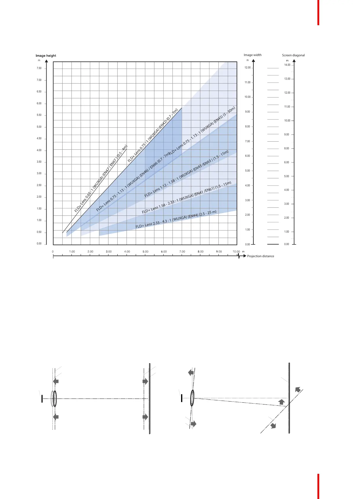
Throw distance, FLD+ / FLDX WUXGA
Projection distance
Image width
m
12.00
11.00
10.00
9.00
8.00
7.00
6.00
5.00
4.00
3.00
2.00
1.00
0.00
Screen diagonal
0.00
1.00
2.00
3.00
4.00
5.00
6.00
8.00
9.00
10.00
11.00
12.00
13.00
14.00
0.00
0.50
1.00
1.50
2.00
2.50
3.00
4.00
4.50
5.00
5.50
6.00
6.50
7.00
7.50
3.50
FLD+ Lens 0.75 : 1 (WUXGA) (EN42) (0.7 - 7m)
FLD+ Lens 0.75 - 1.13 : 1 (WUXGA) (EN45) (5 - 30m)
FLD+ Lens 1.58 - 2.33 : 1 (WUXGA) (EN41 /EN61) (1.5 - 15m)
FLD+ Lens 2.33 - 4.3 : 1 (WUXGA) (EN44) (2.5 - 25 m)
FLD+ Lens 1.12 - 1.58 : 1 (WUXGA) (EN43 /EN63 ) (1.5 - 15m)
FLD+ Lens 0.65 : 1 (WUXGA) (EN47 / EN67 ) (0.5 - 4m)
FLD+ Lens 0.75 - 1.13 : 1 (WUXGA) (EN46) / EN66 (0.7 - 7m)
Image 4–6
4.8 Scheimpflug (Boresight) introduction
What is Scheimpflug?
The lens holder has to be adjusted so that the “sharp focus plane” of the projected image falls together with
the plane of the screen (Fp1→Fp2). This is achieved by changing the distance between the DMD plane and
the lens plane (Lp1→Lp2). The closer the lens plane comes to the DMD plane the further the sharp focus
plane will be. It can occur that you won't be able to get a complete focused image on the screen due to a tilt (or
swing) of the lens plane with respect to the DMD plane. This is also known as Scheimpflug's law. To solve this
the lens plane must be placed parallel with the DMD plane. This can be achieved by turning the lens holder to
remove the tilt (or swing) between lens plane and DMD plane (Lp3→Lp4).
SCREEN
DMD
Lp1
Lp2
Fp1
Fp2
SCREEN
DMD
Lp3
Lp4
Fp3
Fp4
(Scheimpflug)
Image 4–7 Scheimpflug principle
Physical Installation

 Loading...