14. Pin configurations
GPO 5-8
Definition
RJ-45 pin
EXT_GPOU T_6_P
3
EXT_GPOU T_6_N
4
EXT_GPOU T_7_P
5
EXT_GPOU T_7_N
6
EXT_GPOU T_8_P
7
EXT_GPOU T_8_N
8
General Purpose Input:
GPI 1-4
Definition RJ-45 pin
EXT_GPIN_1_P 1
EXT_GPIN_1_N 2
EXT_GPIN_2_P 3
EXT_GPIN_2_N 4
EXT_GPIN_3_P
5
EXT_GPIN_3_N 6
EXT_GPIN_4_P
7
EXT_GPIN_4_N 8
GPI 5-8
Definition RJ-45 pin
EXT_GPIN_5_P 1
EXT_GPIN_5_N 2
EXT_GPIN_6_P 3
EXT_GPIN_6_N 4
EXT_GPIN_7_P
5
EXT_GPIN_7_N 6
EXT_GPIN_8_P
7
EXT_GPIN_8_N
8
About 568A and 568B on an Ethernet connector
RJ-45
TIA/EIA-568A and -568B are two standards for connecting Category 3 and Category 5 wire to co nnectors. Both are appropriate for
high s peed data, though 568B is s omew hat more common for installed wiring and 5 68A is more common in jumpers. There is no
performance advantage either way. The only real difference between the two is the order in which the pairs are used (orange and
green).
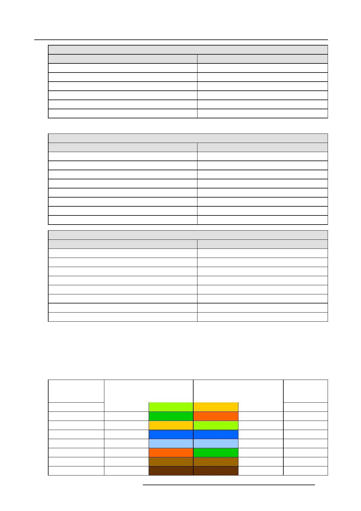
Hold a cable as if to plug it into a wall jack, the locking tab down (contacts facing you). The contacts are numbered 1-8 from left to
right. Here’s what you will see:
RJ-45 Pin Number
(Left >Right copper
side)
568A 568B AES -1-8
1
White/Green White/Orange AES 1&2 +plus
2
Green Orange AES 1&2 +m inus
3
White/Orange White/Green A ES 3 &4 +plus
4 Blue Blue
AES 5&6 + m inu s
5
White/Blue White/Blue A ES 5&6 +plus
6
Orange Green AE S 3&4 +minus
7
White/Brown White/Brown AES 7&8 +plus
8Brown Brown
AES 7&8 + m inu s
R5905963 PROMETHEUS SERIES 09/03/2015 179
 Loading...