5. Lenses & lens holder
5.8 Fixation of the Lens Holder front plate
When fixing the Lens Holder front plate
After performing the pr ocedure for Scheim pflug adjustment or Back Focal L ength adjustment the Lens Holder front plate must be
secured in such a way that it doesn’t disturb the result of the adjustment.
Necessary tools
• 10mm nut driver.
• 3mm Allen wre nch.
• 13mm nut driver.
How to fi x the Lens Holder front plate
Start the fix ation as follows (steps must be followed strictly) :
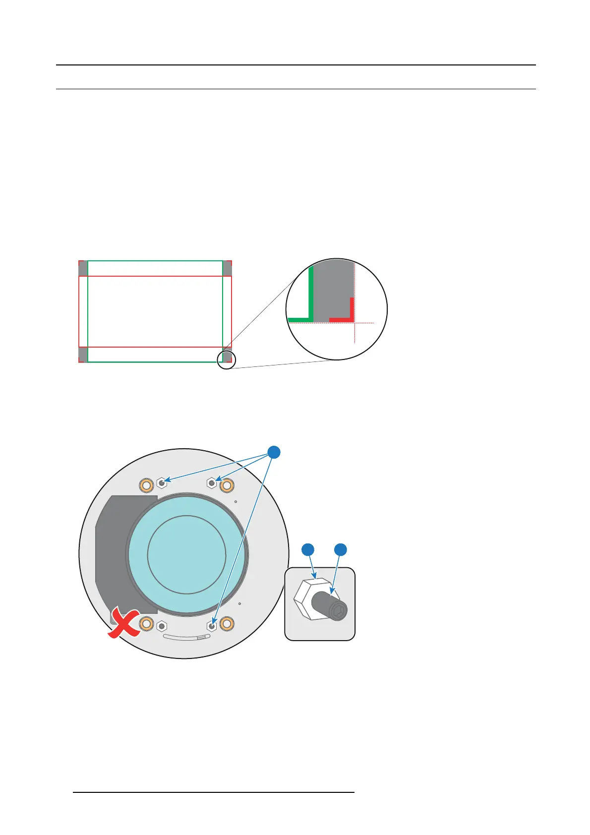
1. Project the framing test pattern for FLAT & SCOPE.
2. Zoom the projected image until the edges of the projected test pattern matches with the edges of the projection sc
reen.
FLAT
SCOPE
Image 5-42
3. Turn in the three set sc rews indicated w ith r eference 11 im age 5-43 without disturbing the projected image. Tighten lightly . Do
not turn in the set screw at the lowe r left of the Lens Holder!
Note: Ensure that the edges of the projected test pattern remain in place on the screen. Any movement of the image will affect
the Scheimp flug adjustment.
4. Fasten the lock nut (reference 21 image 5-43) of the three set screws. Use a 10mm nut driver. E nsure the image doesn’t move.
1121
11
Image 5-43
5. Gently turn (by hand) the S cheim pflug ad justment nut at the lower left of the Lens Holder (reference 4 image 5-44) against the
Lens Holder front plate without disturbing the pr ojected image.
6. Turn in the set screw at the lower left of the Lens Holder (reference 14 image 5-44) without disturbing the projected image. Us e
a 3mm Allen wrench.
Note: Ensure that the edges of the proje
cted test pattern remain in place on the screen. Any movement of the image will affect
the Scheimp flug adjustment.
Tip: Fasten the set screw and the Scheim pfl ug nut alternately, without disturbing the projected image, until the Scheimpflug
nut and set screw are completely tightened.
86
R5905963 PROMETHEUS SERIES 09/03/2015
 Loading...