3. Physical installation
3.5 Connecting the Prometheus I projector with the power net
WARNING: Th e total electrical installation sh ould be pro tected by an appropriate rated and readily accessi-
ble disconnect switch, circuit breakers and ground fault current interrupters. The installation shall be done
according to the lo cal electrical installation codes.
WARNING: Make sure that the voltage range o f projector matches w ith the voltage of the local power net.
CAUTION: The cross-sectional area of the conductors in the Power Supply Cord shall be not less than 4 mm
2
or AWG 10
Necessary tools
• Flat torque screw driver
• Adjustable wrench
Necessary parts
•Certified power supply c ord 4 .0 mm², 10AWG, min. 300V, diameter between 11 mm an d 21 mm
• Circuit breaker max imum 40A
How to connect
1. Remove the back cover.
2. Remove the po wer input cover.
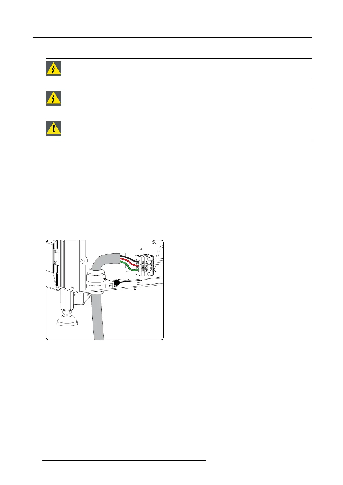
3. Loosen the cable gland fi xation ring (1).
Note: The cable gland (1) is specified for cables w ith a diameter between 11m m and 21mm.
1
Image 3-13
Power cable connection
4. Push the s tripped pow er supply cable th rough the cab
le gland. When using a flexible power cord, ma ke sure that each con ductor
end is provided with a n e n d sleeve.
Fix the cable in the cable gland by securing ring 1 with an adjustable wrench.
5. Connect the power cord with the terminal barrier strip. Use a flat torque screw driver set to 2Nm.
Always connect the ground wire (PE) with the connector indicated with PE on the terminal barrier strip.
Warning: Always connect first the PE wire.
6. Reinstall the power connection cover and the back cover.
32
R5905963 PROMETHEUS SERIES 09/03/2015
 Loading...