116
Calibration
Electrical Limit Switches
This procedure suits limit switches with an electrical input. The in-
put signal is generated with MC5-IS.
Required modules
• The ET module for generating the required electrical signal
(Voltage or Current).
• The E module for detecting the switch’s state.
Preparations
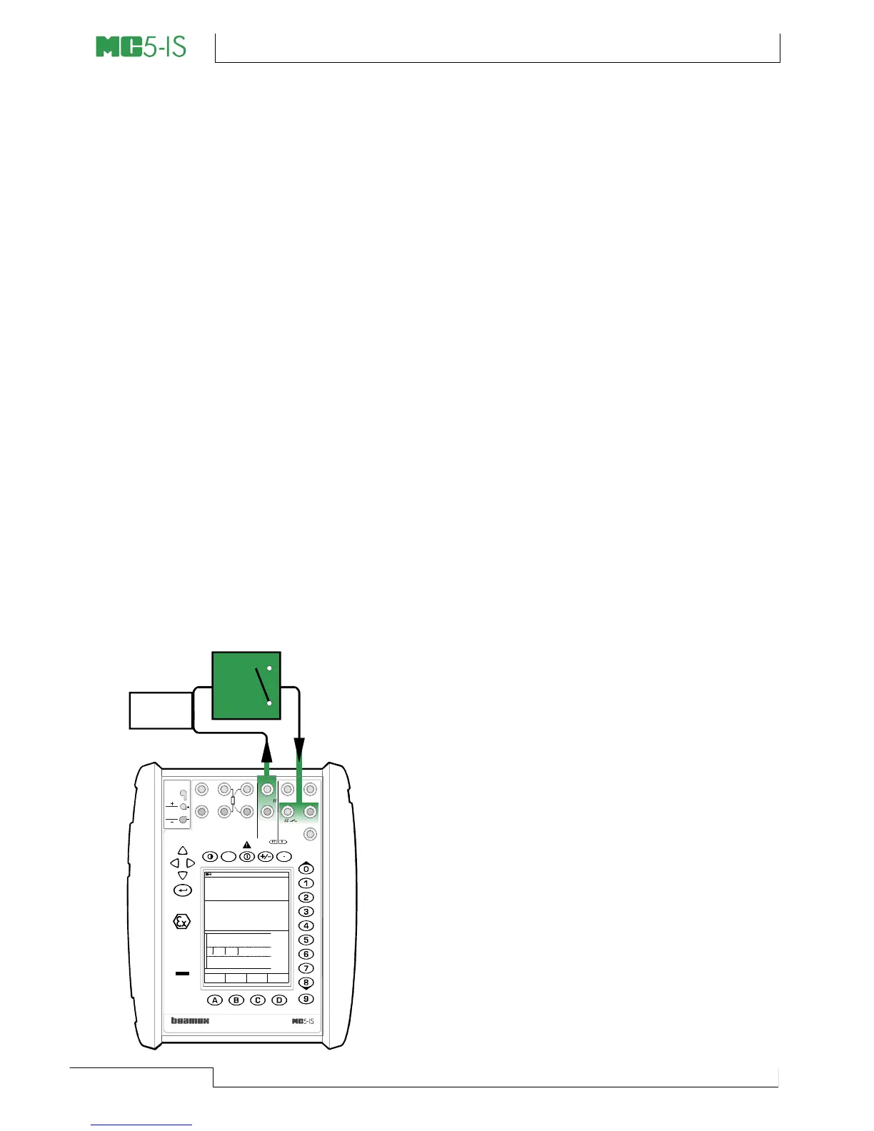
1. Connect the ET module’s terminals
marked “OUTPUT” to the input of the
switch. Add a current source to the loop.
MC5-IS controls the current provided by
the current source.
2. Connect the switch contact to the switch
terminals in the E module.
3. Test the connections in Basic Mode if
needed. To quickly configure the Basic
Mode’s windows, go to Calibration
Mode, select the instrument to be cali-
brated and the Function Key C/Cali-
brate but immediately return to Basic
Mode.
Calibration
1. Move to Calibration Mode and select the
instrument to be calibrated.
2. Start the calibration as is presented in
chapter A Calibration Procedure Us-
ing MC5-IS on page 106. MC5-IS does
the Prescan if it is enabled. During the
prescan, MC5-IS searches for approxi-
mate values for the actuating and
deactuating point. This speeds up the
final test without sacrificing accuracy.
The prescan test is done only once in a
calibration.
• By default, the Prescan is set to on.
If you do not want MC5-IS to per-
form a prescan, disable it (com-
mands D/MENU and 2/Prescan).
When Prescan is set to off, MC5-
IS uses the whole scan range also
during the actual test.
3. The actual test is done automatically:
MC5-IS slowly increases the input sig-
nal until the switch actuates and con-
tinues by decreasing the input signal
until the switch deactuates. MC5-IS’
screen displays the obtained data as
the test advances.
06.10.2000 10:29
Input
Output
V
8.0310
5.023
Voltage [ET: Gen.]
Switch [E: Meas.]
Actuate
Pause
Testing switch limits (4/5)
Deactuate-------
7.000
5.500
4.500
3.000
Current
Source
MULTIFUNCTION CALIBRATOR
T/C, Low V
HART
®
I
meas/sink
V, ,
V, I ,
sink
Com
R, RTD
?
Low V
MEASUREOUTPUT
ET E
T/C INT. RJ
SENSOR MEASURE & SIMULATE
Uo: 16 V
Io: 24 mA
Po: 145 mW
T/C
WIRES
ONLY
II 1 G
EEx ia IIC T4
(Tamb = 50°C)
VTT 02 ATEX 003 X
Ex ia IIC T4
(Tamb = 50°C)
VTT No. Ex-02.011 X
Ui: 30 V
Ii: 215 mA
Pi: 1 W
INPUT
4 w meas
3 w measmeas/sim