82
Advanced Operation and Configuration
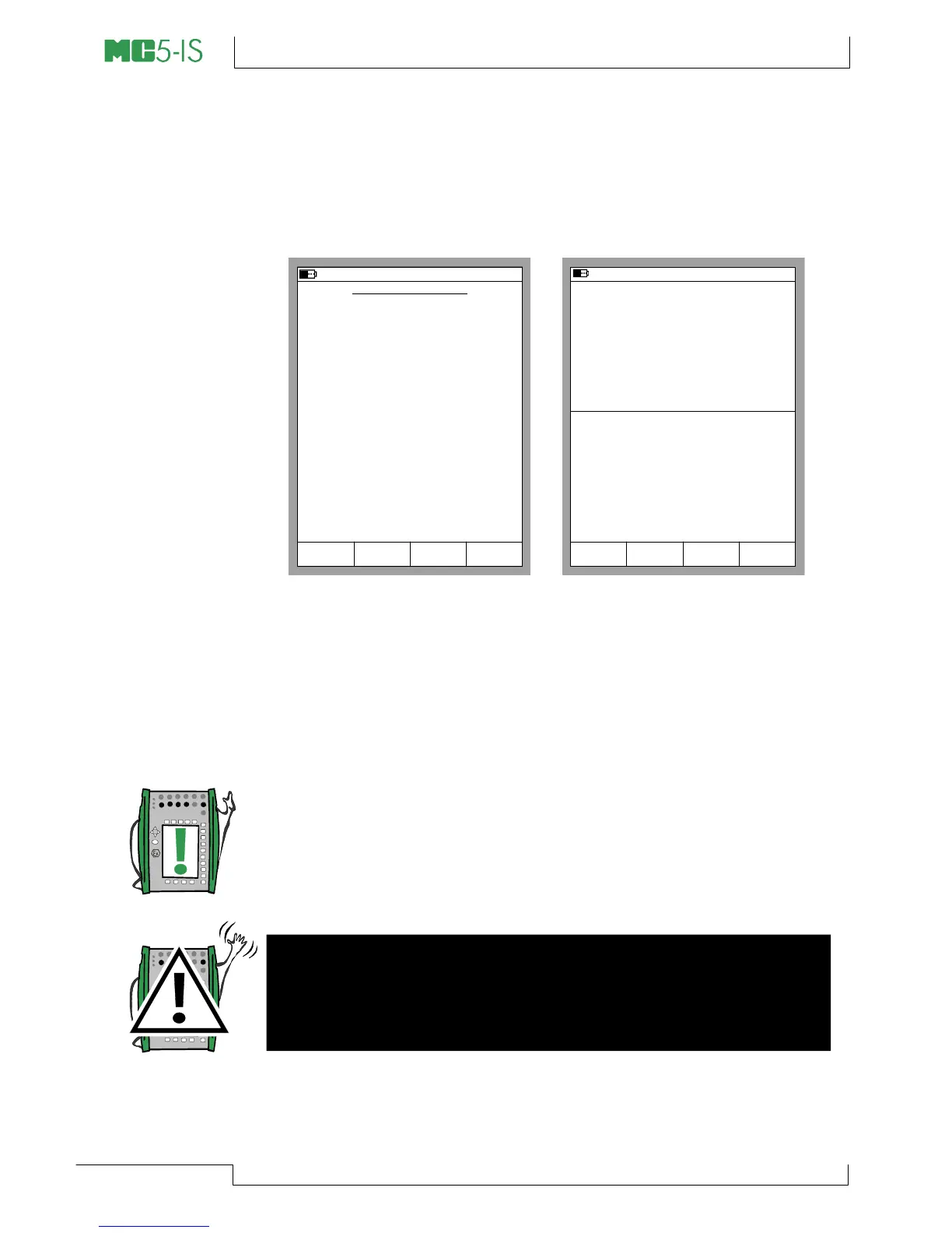
Switch Simulation
Start the Switch Simulation as described in chapter Transmitter/
Switch Simulation on page 80. If the settings of the Basic Mode
windows suit Switch Simulation, a configuration window similar to
the lower left picture is shown.
SWITCH SIMULATION
26.04.2002 14:38
Stop
Ramping
Field StartCancel Edit
INPUT
Port
Pressure
P1:INT2C
kPa
kPa
50.000
40.000
OUTPUT
Port
Voltage
ET: V(gen)
V
V
5.0000
0.5000
Deactuated
Actuated
Deactuating
Actuating
Nominal Points
Switch Limits
30.05.2002 10:32
P2: INT20C/ (50.00/40.00 kPa g)
ET: V(gen)/ (5.000/0.500 V)
gauge
kPa52.034
5.0010
2
OUTPUT
1
INPUT
End
MENU
Measurement V
5.0011
Pause
SWITCH SIMULATION
Select the Switch Type and enter the actuating point and the
deactuating point of the input signal. Also enter the output signal
levels for an actuated output and a deactuated output.
The upper right picture shows the Basic Mode window while Switch
Simulation is active. The second row of the upper window dis-
plays the active port and the actuating and deactuating points. The
second row of the lower window displays the actuated and
deactuated output of the switch.
Note.
To Zero a pressure module during Switch Simulation, press
D/MENU and 7/Zero Pressure Module.
Warning!
Remember to scale the output signal of the Switch Simulation
so that the instrument connected to the output signal loop is not
damaged.