89
Thermocouple Measurement/Simulation, Connections and
Troubleshooting
To accurately measure the thermovoltage caused by the tempera-
ture to be measured, the second thermovoltage caused by the
Reference Junction needs to be compensated. This is done us-
ing one of the Reference Junction compensation methods de-
scribed in the subsequent chapters.
The Reference Junction compensation method has to be chosen
both when measuring and simulating thermocouples.
Internal Reference Junction
MC5-IS’ Internal Reference Junction Mod-
ule is an optional module. To be able to
utilize Internal Reference Junction com-
pensation this optional module has to be
installed into your MC5-IS. If the measur-
ing/simulating port is set to the Internal
Reference Junction Module
(ET: TCi(mea) or ET: TCi(sim)), MC5-IS
automatically selects the Internal Refer-
ence Junction compensation method. No
other Reference Junction compensation
methods are available unless the mea-
suring/simulating port is changed.
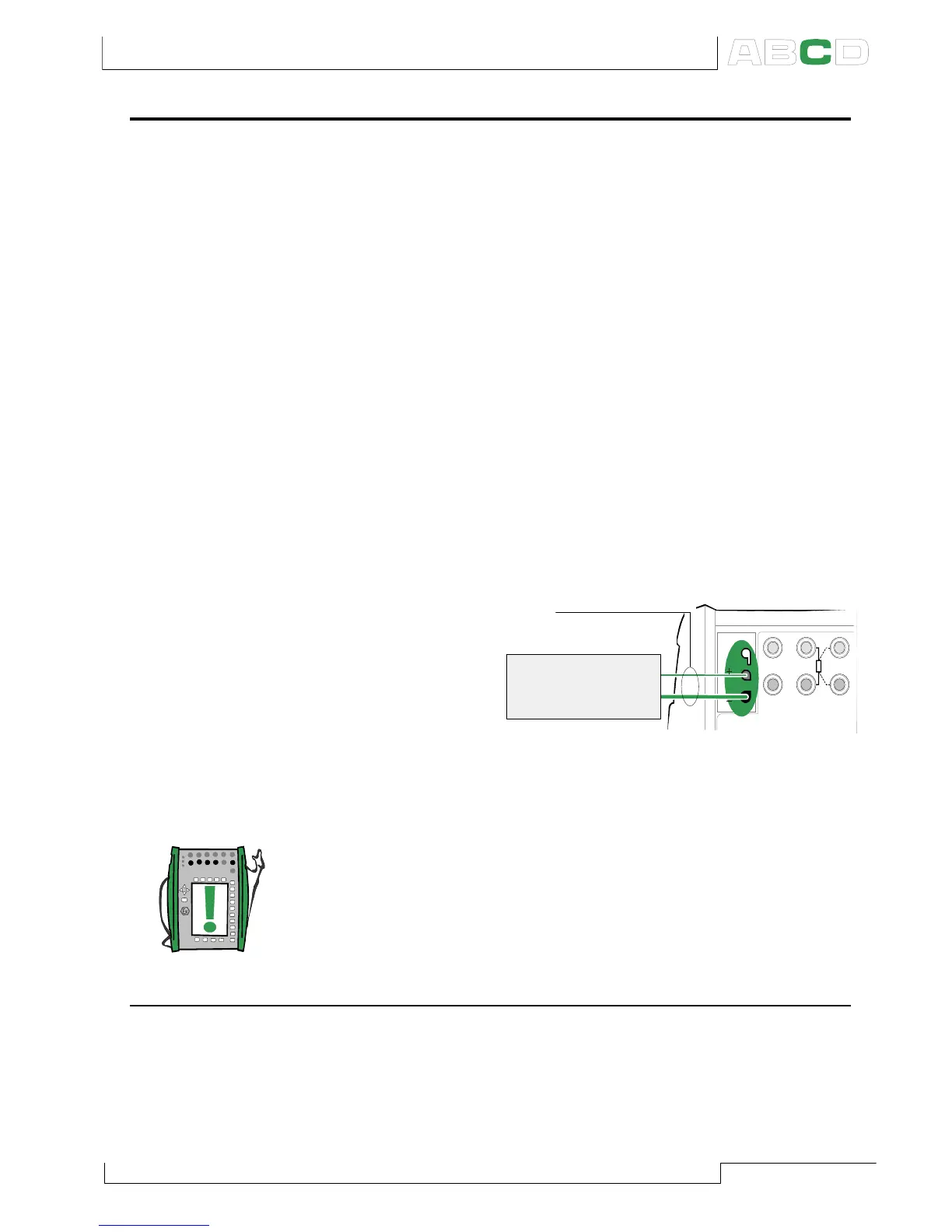
Connection when measuring/simulating
thermovoltage using Internal Reference
Junction Mode:
Note.
The range of the Internal Reference Junction’s temperature com-
pensation is -10 … +50°C (14 … 122 °F).
See also…
External Reference Junction on page 90
T/C, Low V R, RTD
T/C INT. RJ
SENSOR MEASURE & SIMULATE
T/C
WIRES
ONLY
4 w meas
3 w measmeas/sim
T/C sensor
or a
T/C signal receiver
T/C materials
(T/C, extension or
compensation wires)
T/C
WIRES
ONLY
Additional Information