39
Current Measurement
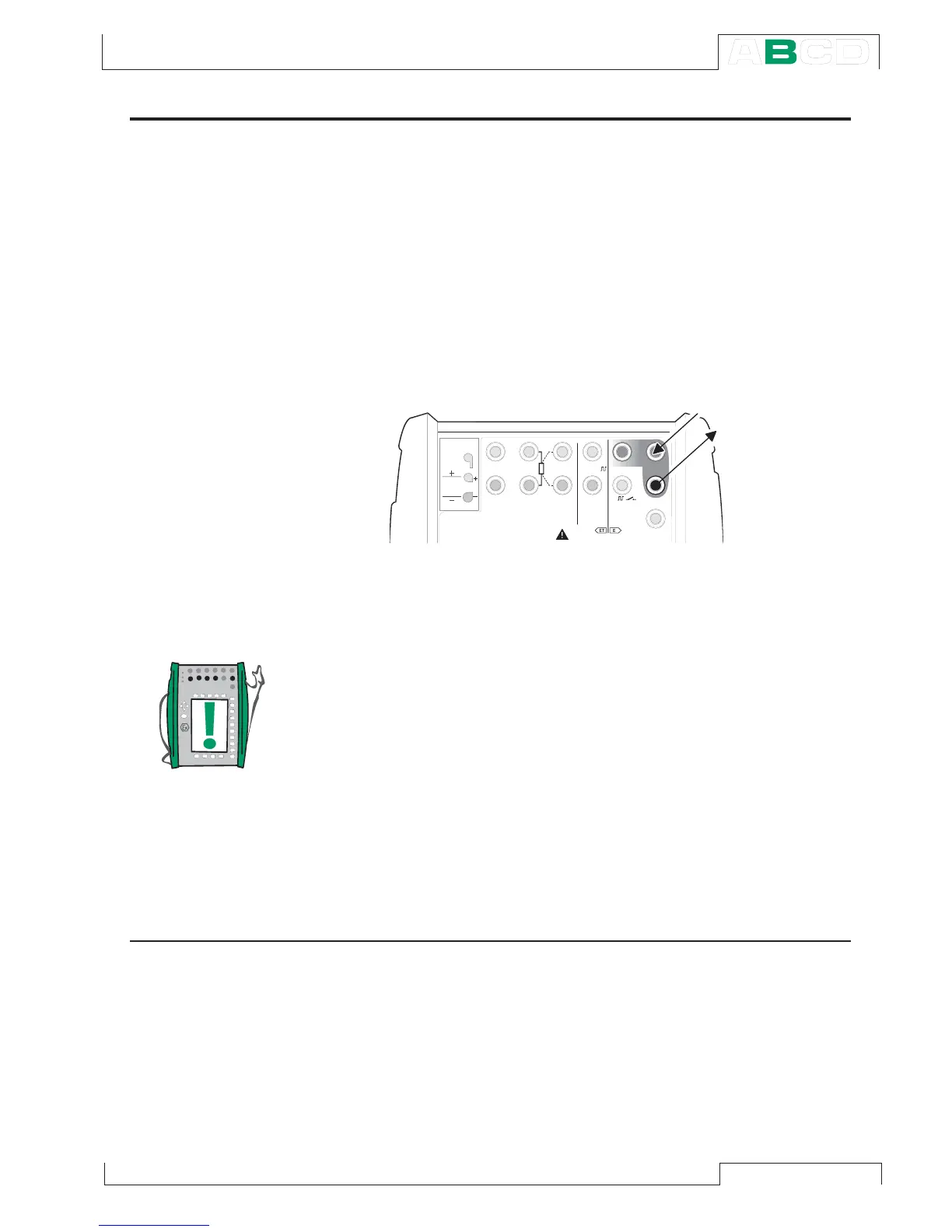
The current measurement terminals are located in the E module. The maximum current is
100 mA.
Required settings Options/description
Quantity Current
Funct/Port E: I(meas)
The active terminals are shown in the picture below.
Notes.
Check the polarity of your connections. The arrows in the previous
picture describe the correct flow of current.
If you are using a transmitter with HART capability, make also a
connection to MC5-IS’ HART terminal. For more information con-
cerning HART connections, see Appendix 1, chapter Connecting
MC5-IS and a HART Instrument on page 131. Information con-
cerning current measurement parallel to a test diode can be found
in part C, chapter Current Measurement Parallel to a Test Diode,
Connections on page 97.
Next…
Current Sink on page 58
Special Measurements on page 51.
Alarm Limit Settings on page 71.
Calibration, see Part D.
T / C , L o w V
H A R T
®
1
m e a s / s i n k
V , ,
V ,
1
,
s i n k
C o m
R , R T D
L o w V
M E A S U R EO U T P U T
E T E
T / C I N T . R J
S E N S O R M E A S U R E & S I M U L A T E
U o : 1 6 V
I o : 2 4 m A
P o : 1 4 5 m W
T / C
W I R E S
O N L Y
4 w m e a s
3 w m e a s
m e a s / s i m
1
m e a s / s i n k
C o m
H A R T
®
Measuring