64
Startup and Basic Operation
RTD and Resistance Simulation
MC5-IS mimics the RTD or the resistor to be measured by the instrument under test. The
instrument under test generates the current for the resistance measurement. MC5-IS
controls the voltage across its terminals so that the resistance (voltage to current ratio)
corresponds to the simulated temperature or resistance. MC5-IS can simulate resistance
between 1 to 4000 ohm.
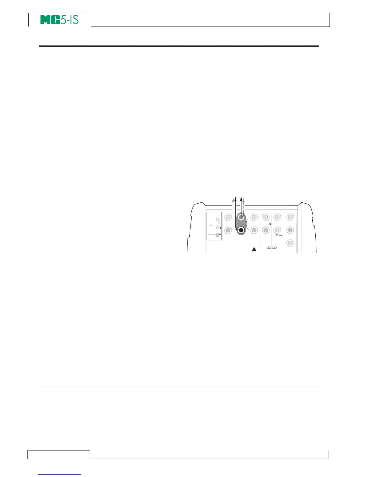
RTD and resistance simulation terminals are located in the
ET module.
Required settings Options/description
Quantity RTD-Temp. (for RTD simulation)
Resistance (for resistance simulation)
Funct/Port ET: RTD(sim) (for RTD simulation)
ET: R(sim) (for resistance simulation)
Sensor Type Available RTD sensors. Only needed
when doing RTD simulation.
The correct resistance value is between the
resistance simulation terminals of the cali-
brator. Use of 2-, 3- or 4-wire connection is
up to the receiver instrument. Use only the
two leftmost
R, RTD terminals with every
wiring option. Connect the possible third
and fourth wire according to the require-
ments of the connected instrument, but use
only the two leftmost R, RTD terminals.
Notes.
In RTD and resistance simulation MC5-IS
monitors the resistance measurement cur-
rent. If the current is too high, it cannot
simulate the right resistance value. In that
case it shows the message “H.CURR”.
Respectively, if the measurement current
is so low that it may affect the accuracy,
the message “L.CURR” is displayed.
Accurate operation of the simulation elec-
tronics requires that the current supplied
by the instrument under test does not vary
rapidly. The simulation result is not accu-
rate if the instrument under test uses AC
current. If the instrument under test uses
pulsed measurement current it should wait
a few milliseconds before starting the mea-
surement after setting the current.
Next…
Thermocouple Measurement (Temperature) on page 49
RTD Measurement (Temperature) on page 48
Resistance Measurement on page 42
Special Generations on page 67
Calibration, see Part D.
T / C , L o w V
H A R T
®
1
m e a s / s i n k
V , ,
V ,
1
,
s i n k
C o m
R , R T D
L o w V
M E A S U R EO U T P U T
E T E
T / C I N T . R J
S E N S O R M E A S U R E & S I M U L A T E
U o : 1 6 V
I o : 2 4 m A
P o : 1 4 5 m W
T / C
W I R E S
O N L Y
4 w m e a s
3 w m e a s
m e a s / s i m
R , R T D