48
Startup and Basic Operation
RTD Measurement (Temperature)
RTD-measurement terminals are located in the ET module.
Required settings Options/description
Quantity RTD-Temp.
Funct/Port ET: RTD(mea)
Sensor Type Available RTD sensors
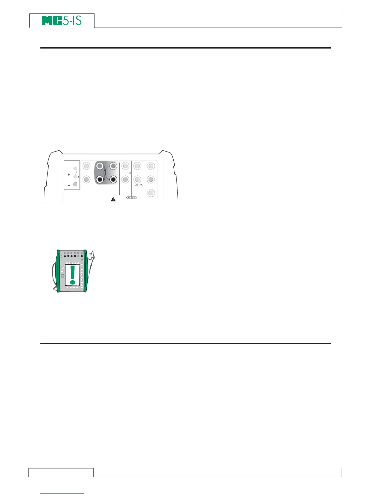
The following picture displays the active
terminals:
The two leftmost terminals are used in 2-
wire systems. MC5-IS automatically checks
the connection and displays the found wir-
ing system (2-wire, 3-wire or 4-wire) in the
measuring window. For more information
concerning wiring options, see Resistance
and RTD Measurement, Connections on
page 95.
Note.
If the measured resistance value is infinite or very high (> 4000
ohm), the text “+OVER” is displayed in the measuring window. This
means that the circuit is broken or the connection is wrong. Wrong
connection may also cause erroneous reading, typically too low. If
necessary, use the 2-wire ohm measurement to check the wiring
before final connection.
Next…
RTD and Resistance Simulation on page 64
Thermocouple Measurement (Temperature) on page 49
Resistance Measurement on page 42
Special Measurements on page 51.
Alarm Limit Settings on page 71.
Calibration, see Part D.
T / C , L o w V
H A R T
®
1
m e a s / s i n k
V , ,
V ,
1
,
s i n k
C o m
R , R T D
L o w V
M E A S U R EO U T P U T
E T E
T / C I N T . R J
S E N S O R M E A S U R E & S I M U L A T E
U o : 1 6 V
I o : 2 4 m A
P o : 1 4 5 m W
T / C
W I R E S
O N L Y
4 w m e a s
3 w m e a s
m e a s / s i m
R , R T D
3 w
4 w