USE OF THE MANUAL
This manual is an easy guide for technicians. All the procedures indicated in the manual are
illustrated in a detailed way and regards the operations of disassembly, assembly, inspection and
repair.
1) The manual is divided in chapters. The name and the relative number, placed in a frame
on the right upper corner of each page, indicating the current chapter.
2) Each chapter is divided in sections. In the left upper part of each page is reported the title of
the current section, written in capital letters.
3) Paragraph title, written in small letters respect to the section title.
4) At the beginning of some sections, to make the procedures of disassembly more clear and
to help the identification of the bike components, are reported the exploded drawings. It is
possible to identify by number the related piece.
5) The exploded drawing is accompanied by a list with the piece name and relative
characteristics.
6) The instructions for the disassembly/assembly operations are described in sequence.
7) Some operations are accompanied by symbols with the purpose to supply more information
and/or possible danger situation for the pilot or motorcycle.
________________________ ENGINE 11
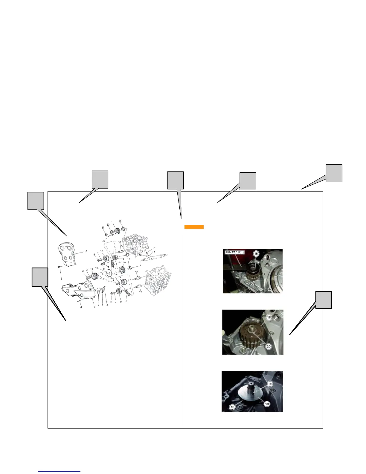
11.8 - HEAD UNIT: TIMING SYSTEM
1) External cover vertical belt
2) Air filter
3) External cover horizontal belt
4) Screw
5) Filter cover
6) Screw
7) Washer
8) Lock nut
9) Complete mobile turnbuckle
10) Oil seal
11) Distribution pulley
12) Tightener pivot
13) Complete fixed turnbuckle
14) Distribution toothed belts
15) Ring nut
16) Tongue
17) Spacer
18) Distribution pulley
19) Pulley washer split
20) Spacer
21) Ring nut
22) Screw
23) Washer
24) Flange spacer
________________________ ENGINE 11
Dismantling of timing system countershaft pulleys
Lock with the tool cod. 88713.1805 the rotation of the motive pulleys on the motor carter.
ATTENTION
In the event that the operation is carried out with the engine in frame, lock the rotation of
the motive pulleys using the tool cod. 88713.2011 mounted on the alternator cover.
Loosen the locknut (15) using the bush that came with tool.
Remove the locknut (15), the spacer (20), and the external pulley (18).
Remove the first tongue (16) on the trip shaft of timing system.
Remove the washer split (19) and the internal pulley (18).
III
5
6
1
3
7
2
4