Operating Instructions ACU
The behavior of the positioning after the required position of the drive is reached can be defined via
the Activity after positioning 463 parameter.
Activity after positioning 463
The drive is stopped with the stopping behavior of Operation
Mode 630.
Wait for positioning signal
The drive is stopped until the next signal edge; with a new edge
of the position signal, it is accelerated in the previous direction
of rotation.
The drive is held until the next signal edge; with a new edge of
the position signal, it is accelerated in the opposite direction of
rotation.
The drive is stopped and the power output stage of the inverter
is switched off.
The drive is stopped for the Time to wait 464; after the waiting
time, it is accelerated in the previous direction of rotation.
The drive is held for the Time to wait 464; after the waiting
time, it is accelerated in the opposite direction of rotation.
The position reached can be maintained for the Time to wait 464, then the drive is accelerated
according to operation mode 4 or 5.
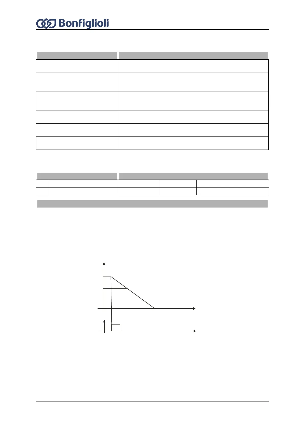
Positioning, Operation Mode 458 = 1
The diagram shows how the positioning to the set positioning distance is effected. The positioning
distance remains constant at different frequency values. At the reference point, the position signal
S
Posi
is generated. Starting from frequency f
max
the positioning is effected at the set Deceleration
(Clockwise) 421 . At a lower frequency value f
1
, the frequency remains constant for some time
before the drive is stopped at the set deceleration.
If, during acceleration or deceleration of the machine, positioning is started by the signal S
Posi
, the
frequency at the time of the positioning signal is maintained.
f
f
max
f
1
S
pos i
U
U
min
t
Digital Input 6
Deceleration (Clockwise) 421