Page 355 of 479
Minimum: This is the minimum range of Process Value (analog input tag)
Example: If an Ear Level transmitter range is 0 to 100, set Minimum = 0, Maximum = 100.
Reverse Scale: True/False. If it is selected, then, zero will be on bottom side and 100 will be at
top side for vertical orientation.
Step: This is the minimum value to reflect change in Bar graph position. Bar Step and Bar
division settings are closely related. If Bar divisions = 50 for a scale value of 0-100, then, if
Step=2, when process value changes by value 2, it shows level value change clearly in
level graph.
Value: Used to enter a process value during design time and to check the bar graph display on
the PC. It requires the operator to enter a value in multiples of the step value.
Otherwise, it is automatically rounded to the closest multiple of the step value.
Is Indicator only: If this is selected, the level graph is used for “Read” purposes only. If it is not
selected, you can use a level graph for write purposes similar to slider to send
a set point from the Recorder to a PLC etc. Just use finger to touch at various
places in Level graph to set the level required.
Value Position: Define position of process value to be displayed during Run time along next to
the Level graph. Available options include None, Top Left, Bottom Right and
Both.
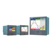
Sections colors: It is configure bands for the sections to show different colors for Labels and
Ticks in Level graph.
Example: Three bands
Section 1, Max % = 60 means, its band is from 0 to 60 %, and it will show labels and ticks in black color.
Section 2, Max % = 80 means its band is from 61 to 80 %.
Section 3, Max % = 100 means its band is from 81 to 100 %.
Note: Band setting is in % for the total Scale defined (Minimum to maximum).