3-102
Confidential
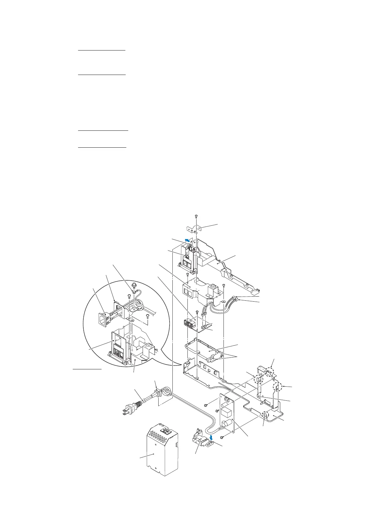
(6) For 100 V series As shown below, unlatch the power cord bush and pull it up from the AC
cord holder. Then release the power cord from the cable guides provided on the AC cord
holder (shown on page 3-104).
For
200 V series Remove screw "j" to release the grounding wire.
(7) Release the power supply shield from three locks "z" on the lower MJ/PS shield and pull it
up.
(8) Press the latch on the PS PCB insulator and pull out the insulator towards you, while
removing the power cord from the insulator.
(9) Remove three screws "h" from the power supply PCB.
(10) For
100 V series Remove screws "e" and "i" and detach the AC cord holder from the
lower MJ/PS shield.
For
200 V series Remove two screws "e" that secure the power inlet bracket and take the
bracket out together with the power inlet. Release the power cord from the cable guides.
Note: If the EXT cap has not been removed, remove it beforehand.
(11) Remove two screws "f" and detach the MJ shield from the lower MJ/PS shield.
(12) Disconnect the main-MJ (LINE) harness and main-MJ (EXT) harness from the MJ PCB
and release them from the cable guides on the MJ PCB insulator.
(13) Remove screw "g" and detach the MJ PCB and MJ PCB insulator from the lower MJ/PS
shield.
(3_067)
"e" and "f": Screw, bind M3x4
"g" and "h": Taptite, cup S M3x6
"i": Screw, bind M4x6
"j": Screw pan (washer) M4x8DB
MJ (LINE) harness (yellow)
MJ (EXT) harness (black)
"i"
Power supply shield
Power supply PCB
Lock "x"
"e"
PS PCB insulator
Lock "z"
Lock "z"
Lock "z"
Square opening
Lower MJ/PS frame
MJ PCB insulator
CN2
Cable
guides
AC cord holder
MJ shield
MJ PCB
Power cord
Latch
Latch
CN1
"e"
"f"
"h"
"h"
Earth frame
"j"
"h"
Power cord
bush
MJ shield
"e"
AC cord holder
Power inlet
Power inlet bracket
Grounding wire
"f"
"g"
200 V series
"f"
 Loading...