Handler Interface
9. Handler Interface
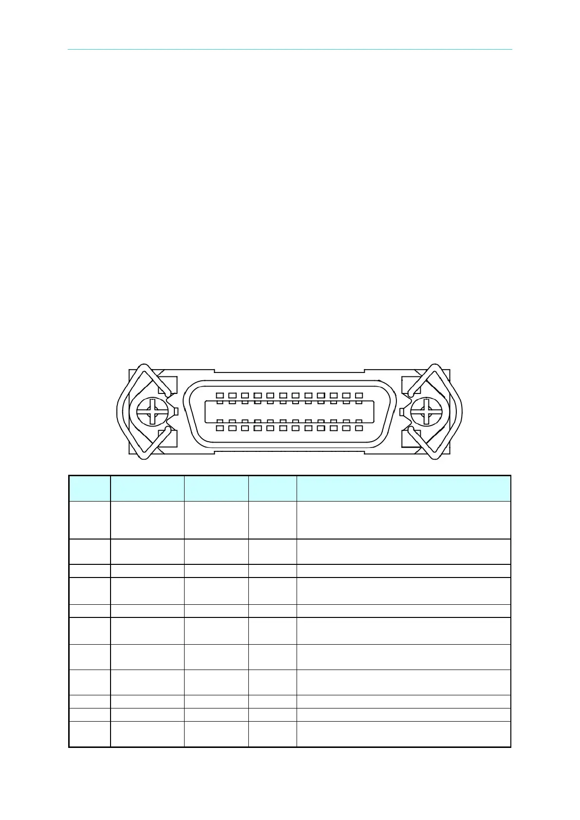
It is connected to external unit by Handler interface. The connector is 24-pin, and its pin
assignment is described as below.
9.1 Specification
9.1.1 Driving Capability
It provides external DC source to +Vext terminal with input voltage range +5V~+24V while
executing automated measurement. Use GND pin for low voltage terminal of external DC
voltage input & input/output signal. The maximum output current of output signal terminal is
5mA. The inside of the tester provides a set of +5V DC voltage which supports 50mA output
current maximally.
9.1.2 Pin Assignment
Pin No.
Signal
Description
1 /EXT Input (I/P) X
It turns from HIGH to LOW when external
input is START signal. The detail description
as Figure 9-1 shows.
2 /RESET Input (I/P) X
1. Reset output is OFF status.
2. Reset O/P PIN returns to default value.
4
#
Output (O/P)
X
Reserved output signal #1
External DC source grounding
9
#
Output (O/P)
X
Reserved output signal#2
10 VEXT Input (I/P) X
External DC voltage power input, input
voltage range is from +5Vdc to 24Vdc.
11 Vext_5V Output (O/P)
X
External DC voltage +5V (maximum output
current is 50mA)
15 /PASS Output (O/P)
Hi-Z
Total PASS contains Compare pass, Contact
check pass, Charge/Discharge pass and