A112102 PD Test Checking Kit (Option)
8.3.1 11210 and A112102 Setup
Assuming the test voltage is 500V when not connected to DUT, the expected PD simulation
signal level is about 30. From Table 8-2, we know the capacitance is #5 as the VPD and CPD
level is about 27~33.
8.3.1.1 Setting Test Parameters
For the IR/LC measurement related settings and parameters, please see section 5.3.1, 5.3.2
and 5.3.3. See section 6.4 and 6.4.2 for setting PD Compare parameters.
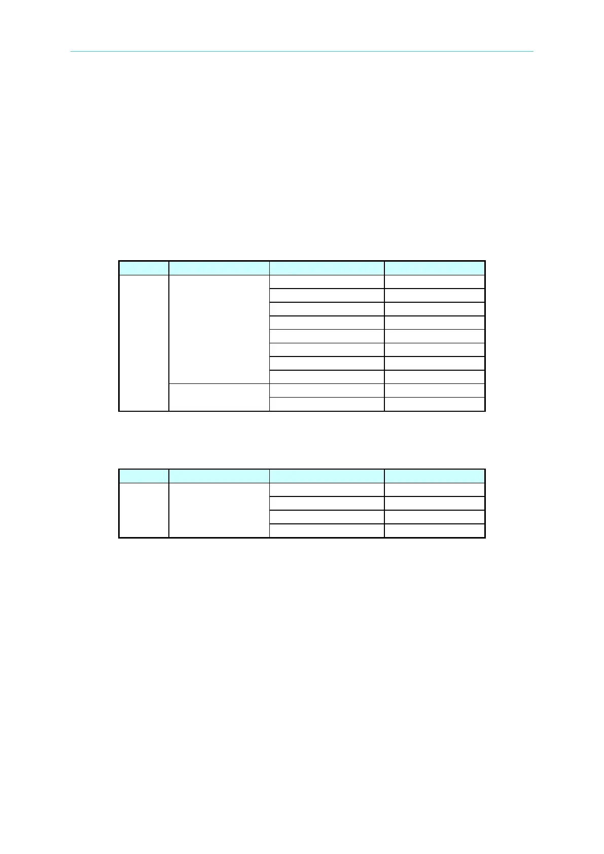
11210
Insulation Test
PD Compare
8.3.1.2 Setting A112102 Parameters
A112102
PD Simulation
Test
Setting Voltage Trigger:
Since the test voltage is 500V, the A112102 will send out PD simulation signals as long as the
voltage trigger is set to less than the test voltage (500V). In this example, the trigger is set to
20V.
Setting PD Capacitance:
For 500V test voltage, select #5 as the mapping capacitance tha has 27~33 of occurrences.
Setting PD Interval:
The times of PD simulation signal is related to the PD Interval. VPD is the PD signals occurred
within Charge Time while CPD is the PD signal occurred in Dwell Time and Test Time. The PD
simulation signal occurrence times can be calculated following this rule.
VPD times= (Charge Time)/ PD Interval +1
CPD times = (Dwell Time+Test Time)/ PD Interval