Description of Panel
4-1
4. Description of Panel
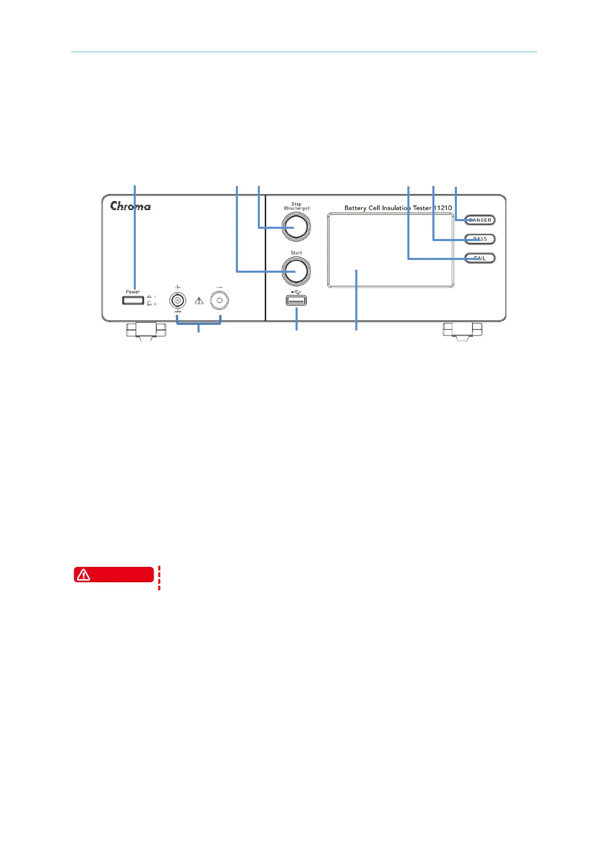
4.1 Front Panel
(1) Touch Panel Display
The display of this tester is a 480RGB X 272 Touch Panel Display. All function setting
options can click or scroll on touch panel display for selection, all measurements and
settings can be clearly displayed and seen.
(2) Power Switch
It switches the power to on or off. This key pressed means power on and unpressed
means power off.
(3) LEAKAGE CURRENT Terminal
The leakage current test terminal is composed of one notch type terminal and BNC
connector, and is connected DUT directly by a test cable. Be sure that the meter is in stop
testing or discharge mode when connecting or disconnecting it to a DUT as the output
voltage of its negative terminal (red notch type terminal) is pretty high [V(DC) = 0V ~
-1000V].
Don’t touch the test terminal or DUT while test status LED lights or
blinking.
(4) USB Interface (A-Type)
Standard FLASH MEMORY HOST interface can save and read test procedure and data
as well as image capture for saving PD Analyzer in the file format of PNG. The maximum
capacity only can support USB disk with 128GB and in the format of FAT32.
(5) START Key
Press this key to start testing.
(6) STOP Key
The tester will return to standby test status immediately and cut off the output once
pressing this key. It also can be utilized to clear the warning message.