2. If HP 34401 is used, the DVM1 and DVM2 can be connected to the
front and rear measurement input terminal respectively.
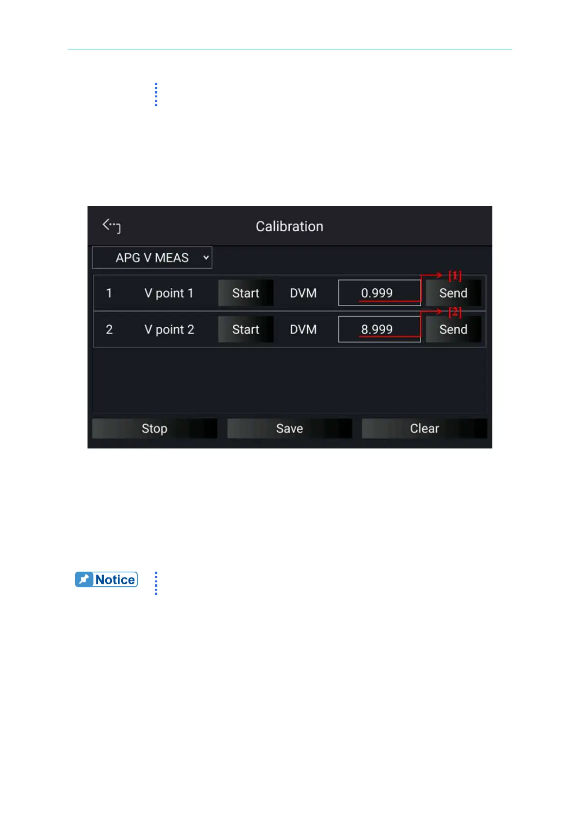
2. When in APG V MEAS page and the wires are correctly connected, tap “START” next to
V point 1 to calibrate the first point voltage.
3. The system will set the output voltage on the rear panel to approx. 1.0V (TP112). Use
DVM1 to measure the Power Supply. Enter the measured voltage to position [1] and tap
“SEND” to confirm.
Figure 3-75
4. Next, tap “START” next to V point 2 to calibrate the second point voltage. The system
will set the output voltage on the rear panel to 9.0V (TP112). Use DVM1 to measure the
Power Supply. Enter the measured voltage to position [2] and tap “SEND” to confirm.
5. When the APG voltage calibrations are complete, tap “STOP” to exit the calibration
procedure. To save the calibration data, tap “SAVE”, and tap “CLEAR” to delete the
calibration parameters if there is no need to save them.
Calibration point will be different for other models, please follow above
instructions for all models.

 Loading...