Installation
2-9
2.4 Remote Sensing
2.4.1 Correct Connection
1. Connecting remote sensing wires correctly will ensure the output voltage is the set
voltage at the end of the output cable. The DC power supply is able to compensate 4%
V_MAX line voltage drop.
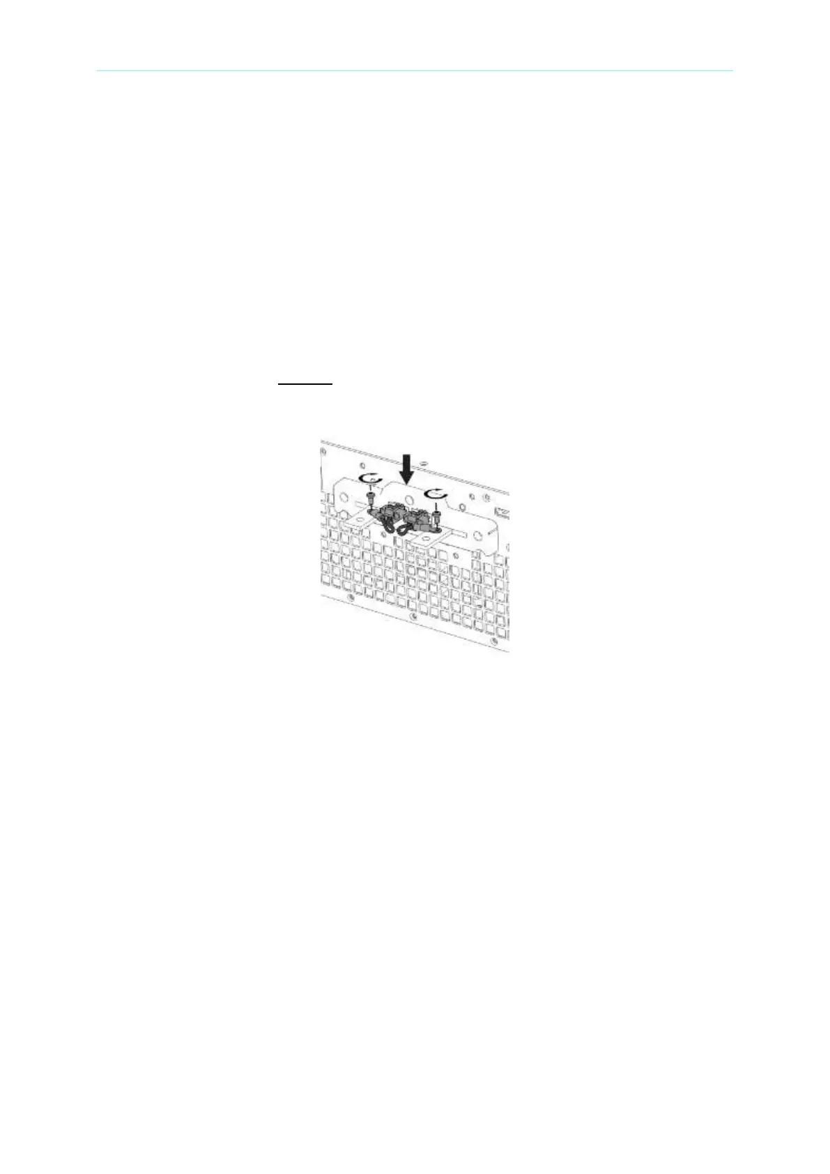
2. Figure 2-2 shows the correct connection. Use two wires to connect the positive/negative
connector of load to the remote sensing connector on the rear panel. The connecting
wire diameter must be 22AWG, and its withstand voltage should meet the 3kV
specification.
3. Though remote sensing is able to compensate the voltage drop, if the line loss is too
large (see specification) it will cause protection error on remote sensing.
4. Remote sensing wire must be connected to the DC power supply’s local output OR the
UUT’s remote input.
Figure 2-2
2.4.2 Reverse Connection of Remote Sensing Wire
Polarity
The polarity of remote sensing wire must be connected correctly, the “+” terminal is
connected to the “+” side of the unit under test and the “–” terminal must be connected to the
“–” side of the unit under test. If the polarity is connected reversely, the output will drop to 0V
and prompt an error message “SENSE FAULT” as Figure 2-3 shows.

 Loading...

