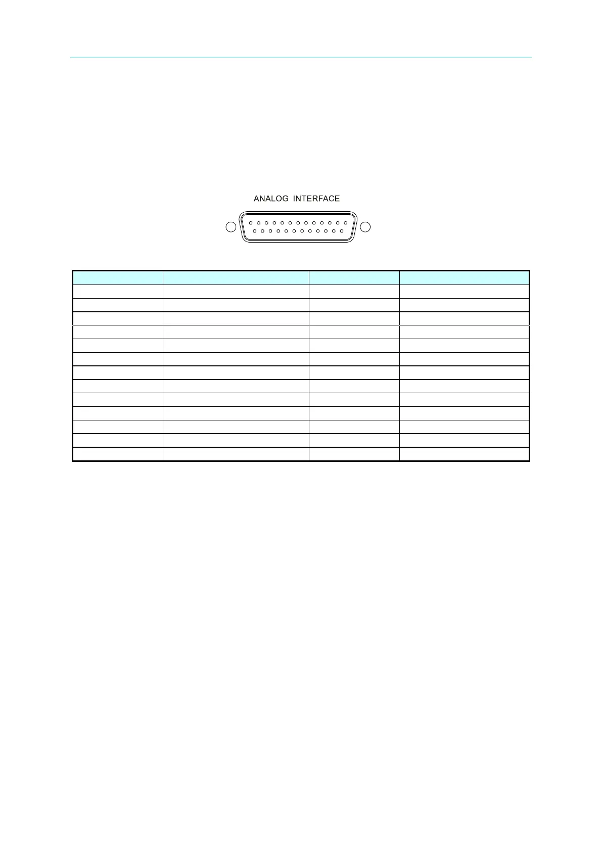
(1) PIN 1: DCOUT_ON, when the output voltage exceeds VDC_R, the DCOUT_ON will turn
to HIGH. When the DC power supply output voltage is lower than the VDC_F setting,
the DCOUT_ON will turn to LOW.
(2) PIN 2: DC_ON_ST, when DC ON, it outputs signal to trigger TTL Level to Active High.
(3) PIN 3: INTERLOCK, this function allows users to control the power supply for temporary
OFF, see section 3.2.3.4.4 for detail description.
(4) PIN 4: DO1, this pin is HIGH when in CV mode and LOW when in CC mode.
(5) PIN 5: N.C.
(6) PIN 6: DI2, it provides External Load ON/OFF function for you to control it. If DI1 and
DI2 are set to External Load ON/OFF, both signals need to be HIGH to set the Load
OFF and on the contrary, both signals need to be LOW to set the Load ON.
(7) PIN 7: KEYPRO, it is the foolproof mechanism for series/parallel hardware connection
(KEYPRO), 0: Series, 1: Standalone and parallel.
(8) PIN 8: AIO_S_SET_V, Source current setting only that allows you to set in “voltage
form” with input voltage range from 0 to 10V, see section 3.2.4.1.1 APG for detail
information.
(9) PIN 9: AIO_L_SET_V, Load current setting only that allows you to set in “voltage form”
with input voltage range from 0 to 10V, see section 3.2.4.1.1 APG for detail information.
(10) PIN 10: AIO_MEAS_V, current measurement only that allows you to set in “voltage
form” with input voltage range from -10V to 10V, see section 3.2.4.1.1 APG for detail
information.
(11) PIN 11: N.C.

 Loading...

