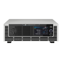
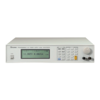
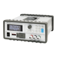
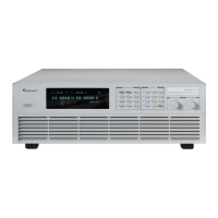
Programmable Bidirectional DC Power Supply 62000D Series
Operating and Programming Manual
xiii
Table of Contents
1. Overview ........................................................................................................... 1-1
1.1 Introduction ......................................................................................................... 1-1
1.2 System Functions ............................................................................................... 1-1
1.2.1 Operation Mode .......................................................................................... 1-1
1.2.2 Protection .................................................................................................... 1-1
1.2.3 Output and Indicators .................................................................................. 1-2
1.2.4 Control Signals for Input .............................................................................. 1-2
1.2.5 Measuring and Editing ................................................................................. 1-2
1.3 Specifications ...................................................................................................... 1-2
1.4 Function Buttons ............................................................................................... 1-14
1.4.1 Front Panel ............................................................................................... 1-14
1.4.2 Rear Panel ................................................................................................ 1-15
2. Installation ........................................................................................................ 2-1
2.1 Checking the Package ........................................................................................ 2-1
2.1.1 Maintenance and Cleaning .......................................................................... 2-4
2.2 Preparation for Use ............................................................................................. 2-5
2.2.1 Normal Environment Conditions .................................................................. 2-5
2.3 Requirements of Input Power .............................................................................. 2-5
2.3.1 Ratings ........................................................................................................ 2-5
2.3.2 Input Connection ......................................................................................... 2-6
2.4 Remote Sensing ................................................................................................. 2-9
2.4.1 Correct Connection ..................................................................................... 2-9
2.4.2 Reverse Connection of Remote Sensing Wire Polarity ................................ 2-9
2.5 Output Connection ............................................................................................ 2-10
2.5.1 Rear Panel Output..................................................................................... 2-10
2.5.2 Specification of Connecting Wire ............................................................... 2-13
2.5.3 Specification of Parallel Capacitance ........................................................ 2-13
2.5.4 Installing the Handle .................................................................................. 2-13
2.6 Power On Procedure......................................................................................... 2-14
3. Manual Operation ............................................................................................. 3-1
3.1 Introduction ......................................................................................................... 3-1
3.2 Menu for Setup ................................................................................................... 3-1
3.2.1 Meas. & Setup ............................................................................................. 3-3
3.2.1.1 Source & Load Mode ............................................................................... 3-3
3.2.1.2 Source Mode ........................................................................................... 3-4
3.2.1.3 Load Mode .............................................................................................. 3-5
3.2.2 Output Setup ............................................................................................... 3-6
3.2.2.1 Response CV .......................................................................................... 3-7
3.2.2.2 Response CC .......................................................................................... 3-7
3.2.2.3 V Limit ..................................................................................................... 3-7
3.2.2.4 I Limit ...................................................................................................... 3-7
3.2.2.5 P Limit ..................................................................................................... 3-7
3.2.2.6 V SLEW RATE ........................................................................................ 3-8
3.2.2.7 I SLEW RATE.......................................................................................... 3-8
3.2.2.8 Setting DC_ON ........................................................................................ 3-9
3.2.3 System Setup ............................................................................................ 3-10
3.2.3.1 System Information ............................................................................... 3-10
3.2.3.2 Factory Setup ........................................................................................ 3-12
3.2.3.3 Basic Setting ......................................................................................... 3-13
3.2.3.4 Protection .............................................................................................. 3-14

 Loading...


