Overview
1-15
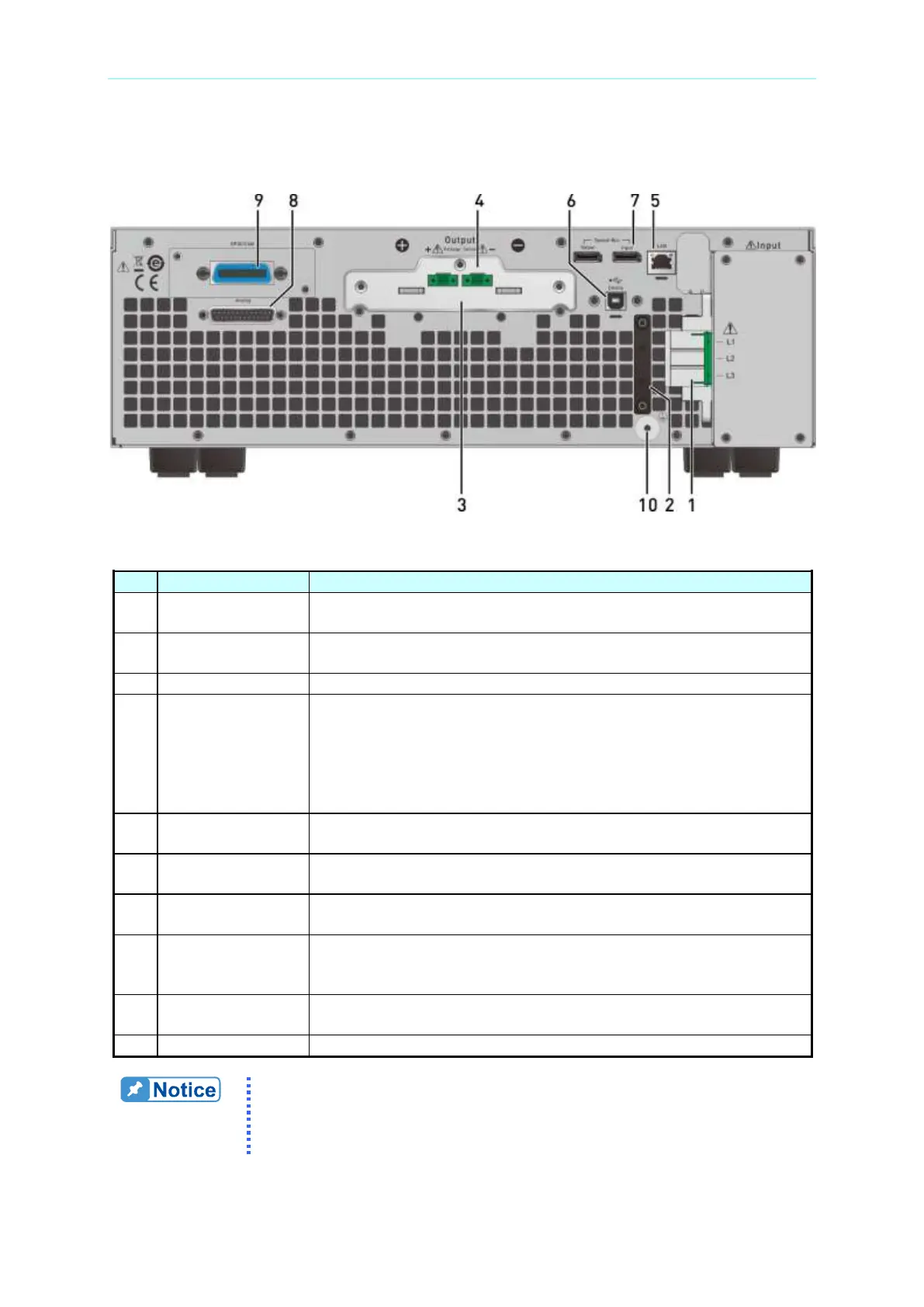
1.4.2 Rear Panel
Figure 1-3 Rear Panel of 62000D Series Models
Table 1-4 Rear Panel Description
AC power input connector.
AC power cord
anti-pulling device
Connects to the AC power cord connector to prevent the cord
from loosening due to external force during operation.
The output terminals of DC power supply.
Connecting this connector to load can compensate the voltage
drop generated due to cable resistance. Be sure to connect the
remote sense connector “+” to the positive output terminal of the
device under test and “–” connector to the negative output
terminal of the device under test. Reversing these connectors
could cause damage to the power supply or the device under test.
The remote controller uses ETHERNET bus to connect to PC for
remote operation.
The remote controller uses USB bus to connect to PC for remote
operation.
It is for serial/parallel data transmission. (Remove this cable if the
power supply is not connected in series or parallel.)
ANALOG interface
signal connecting
terminal
There are 25 pins signals that include APG input/output terminals
and system status signal terminals. See Appendix A for detail pin
assignments.
GPIB/CAN (option)
connector
Used for GPIB/CAN control via and external PC for remote
operation.
This terminal is to connect the power supply to earth ground.
Item 9 in Figure 1-3 is an optional GPIB/CAN interface of 62000D
selected by the user. A blank panel will be installed if no interface is
selected.

 Loading...

