Manual Operation
3-47
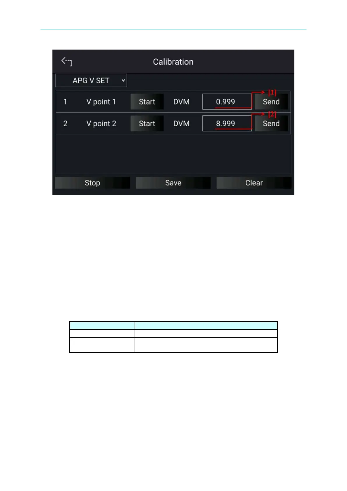
Figure 3-72
4. Next, tap “START” next to V point 2 to calibrate the second point voltage. User will be
prompted to input about 9.0V voltage signal (TP120). Adjust the Power Supply to
9V±0.1V and use DVM1 to measure the Power Supply. Enter the measured voltage to
position [2] and tap “SEND” to confirm.
5. When the APG voltage calibrations are done, tap “STOP” to exit the calibration
procedure. To save the calibration data, tap “SAVE”, and tap “CLEAR” to delete the
calibration parameters if there is no need to save them.
3.2.4.4.4 APG Voltage Measurement Calibration
Table 3-8 lists the hardware requirements for APG voltage measurement calibration.
Table 3-8

 Loading...

