1. When entering into the Calibration page, be sure to check the
interface connection on the rear panel is correct.
2. Calibration points will be different for other models, please operate
it following the instructions displayed.
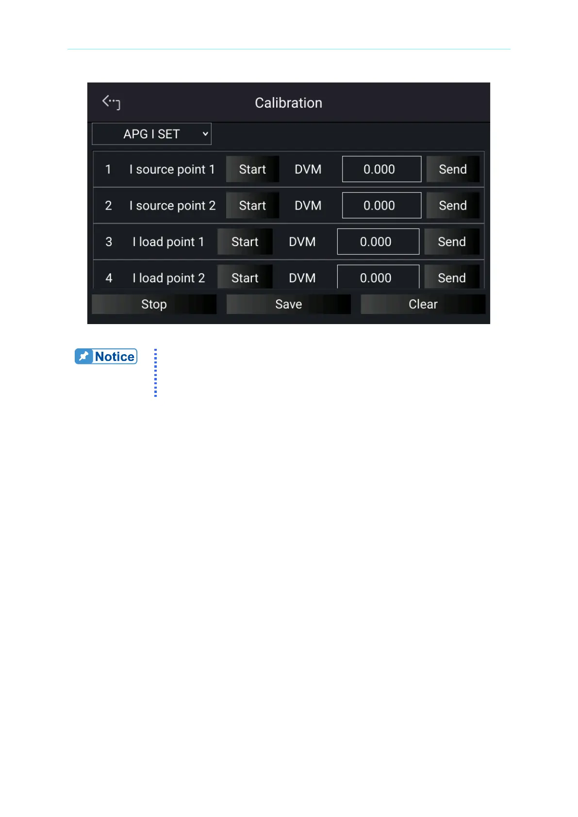
3. When in APG I SET page and the wires are correctly connected, tap “START” next to I
source point 1 to calibrate the first point current.
4. It will request you to input about 1V voltage signal (TP108). Adjust the Power Supply to
1V±0.1V and use DVM1 to measure the Power Supply. Enter the measured voltage to
position [1] and tap “SEND” to confirm as Figure 3-78 shows.
5. Next, tap “START” next to I source point 2 to calibrate the second point current. Adjust
the Power Supply to 9V±0.1V and use DVM1 to measure the Power Supply. Enter the
measured voltage to position [2] and tap “SEND” to confirm as Figure 3-78 shows.
6. Tap “START” next to I load point 1 to calibrate the first point positive current. It will
request you to input about 1V voltage signal (TP109). Adjust the Power Supply to
1V±0.1V and use DVM2 to measure the Power Supply. Enter the measured voltage to
position [3] and tap “SEND” to confirm as Figure 3-78 shows.
7. Next, tap “START” next to I load point 2 to calibrate the second point negative current.
Adjust the Power Supply to 9V±0.1V and use DVM2 to measure the Power Supply.
Enter the measured voltage to position [4] and tap “SEND” to confirm as Figure 3-78
shows.

 Loading...

