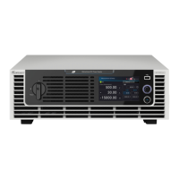
Programmable Bidirectional DC Power Supply 62000D Series
Operating and Programming Manual
xv
5. Remote Operation ............................................................................................ 5-1
5.1 Overview ............................................................................................................. 5-1
5.1.1 USB Interface .............................................................................................. 5-1
5.1.2 Setting GPIB and Ethernet Parameters ....................................................... 5-1
5.1.3 Ethernet Remote Control ............................................................................. 5-1
5.2 GPIB Function of 62000D Series ........................................................................ 5-2
5.3 Introduction to Programming ............................................................................... 5-2
5.3.1 Conventions ................................................................................................ 5-2
5.3.2 Numerical Data Formats.............................................................................. 5-2
5.3.3 Boolean Data Format .................................................................................. 5-3
5.3.4 Character Data Format ................................................................................ 5-3
5.3.5 Basic Definition ........................................................................................... 5-3
5.3.5.1 Command Tree Structure ........................................................................ 5-3
5.3.5.2 Program Headers .................................................................................... 5-3
5.3.5.3 Common Command and Query Headers ................................................. 5-4
5.3.5.4 Instrument-Controlled Headers ................................................................ 5-4
5.3.5.5 Program Header Separator (:) ................................................................. 5-4
5.3.5.6 Program Message ................................................................................... 5-4
5.3.5.7 Program Message Unit ............................................................................ 5-4
5.3.5.7.1 Program Message Unit Separator (;) ................................................. 5-4
5.3.5.7.2 Program Message Terminator (<PMT>) ............................................ 5-4
5.4 Traversal of Command Tree ............................................................................... 5-5
5.5 Execution Order .................................................................................................. 5-5
5.6 DC Power Supply Commands ............................................................................. 5-5
5.6.1 Common Command Syntax ........................................................................ 5-8
5.6.2 Specific Commands for 62000D Series ..................................................... 5-12
5.6.2.1 Subsystem ............................................................................................ 5-12
5.6.2.2 CONFIGURE ......................................................................................... 5-13
5.6.2.3 SOURCE Subsystem ............................................................................ 5-17
5.6.2.4 LOAD Subsystem .................................................................................. 5-21
5.6.2.5 FETCH Subsystem ................................................................................ 5-22
5.6.2.6 MEASURE Subsystem .......................................................................... 5-23
5.6.2.7 PROGRAM Subsystem ......................................................................... 5-23
5.6.2.8 SYSTEM Subsystem ............................................................................. 5-28
5.6.2.9 INSTRUMENT Subsystem .................................................................... 5-33
6. Operation Theory ............................................................................................. 6-1
6.1 Overview ............................................................................................................. 6-1
7. Self Test and Troubleshooting ........................................................................ 7-1
7.1 Overview ............................................................................................................. 7-1
7.2 Troubleshooting .................................................................................................. 7-1
Appendix A Analog Interface Pin Assignments ....................................................... A-1
Appendix B List of Protection ................................................................................... B-1

 Loading...


