Table 48. ASR 5000 PFU Wiring Diagram Descriptions
Two 2-hole lugs are required: one for return (RTN) and one for power (-VDC). The PFU 0.3125-inch posts spaced 0.88-
inch on center.
Method of connection: PFU - Flat Washer - Lug - Lock-Washer - Nut (9/16-inch). The nut(s) must be torqued to 50 in-lb.
(5.65 N-m).
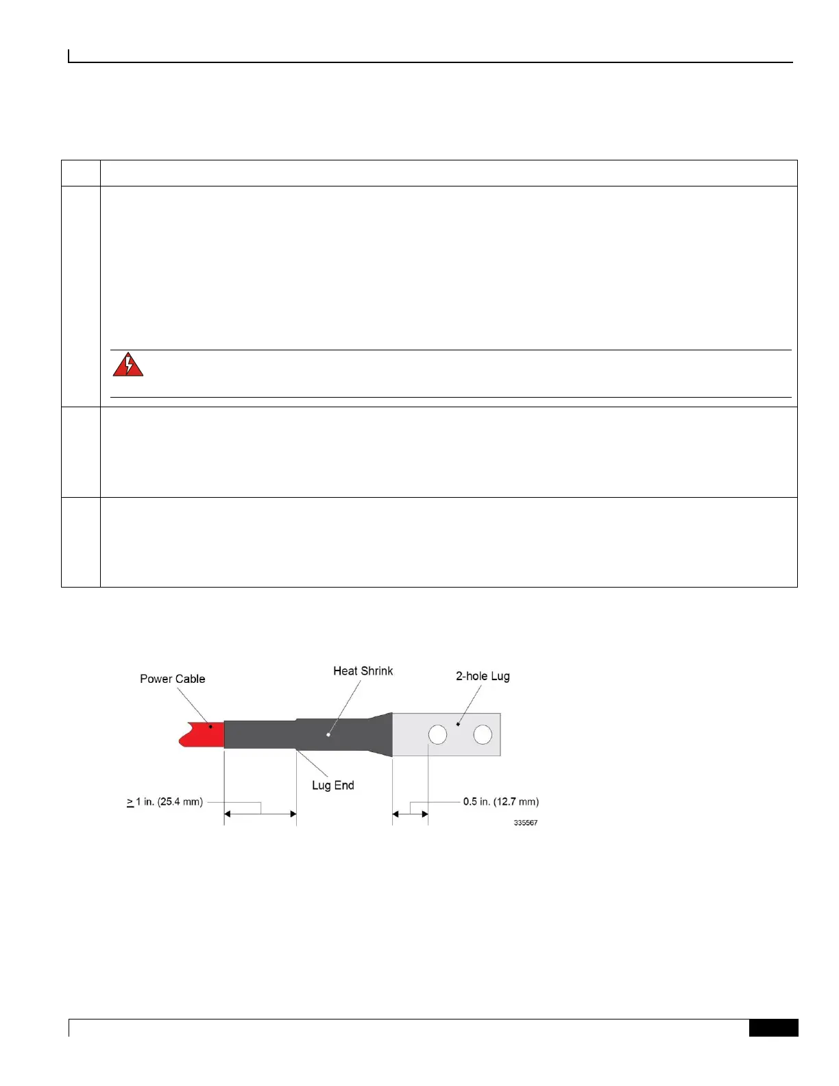
The lug must be covered with heat shrink tubing. The heat shrink tubing should begin approximately 1 inch (25.4 mm)
before the lug and extend to within 0.5 inch (12.7 mm) of the lugs first hole. Slide the tubing over the cable end before
crimping the lug to the cable. Refer to the following figure.
Use the Panduit® lugs supplied with the chassis (LCD1-56C-E). Crimp them to the cable ends with a Panduit crimp tool
part number CT-920 (die color: green P37 (CD-920-1).
WARNING: The plastic terminal cover must be installed over power and return lugs at all times. Die
angeschlossenen Kabelschuhe muessen mit der Plastikabdeckung gesichert sein.
Power Cables (PDP-to-Chassis):
Cable length: Not more than 9 feet (2.7 meters) one way
Voltage drop: 0.3v
Cable size: 1 AWG or greater
Power Cables (PDF-to-PDP):
Cable length: not more than 40 feet (12.2 meters) one way
Voltage drop: 0.3v
Cable size: 350,000 Circular Mils
Figure 50. Power Lug

 Loading...


