▀ Interface Specifications
▄ ASR 5000 Installation Guide
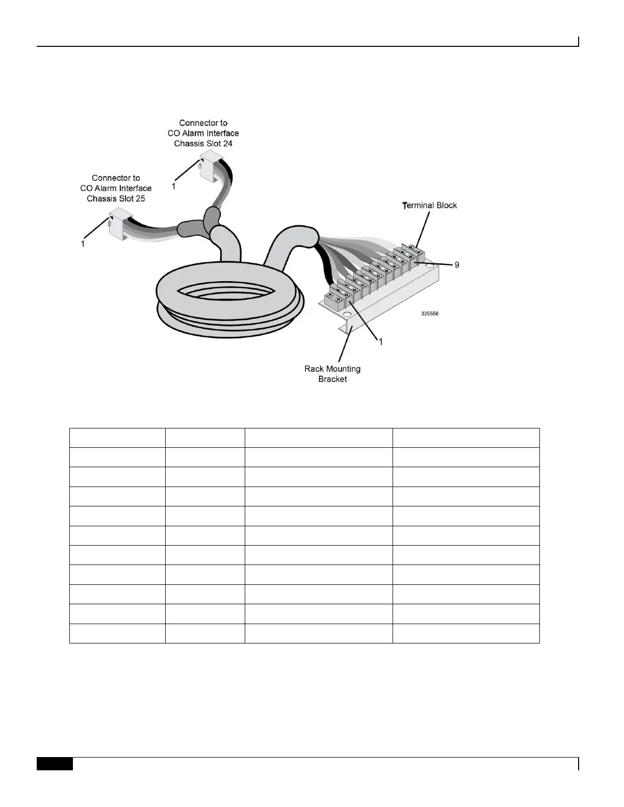
Figure 64. SPIO CO Alarms Cable Assembly
Table 95. CO Alarms Cable Pinout
Cable Terminal Block Position No.
Major Alarm - Normally closed
Major Alarm - Normally open
Minor Alarm - Normally closed
Minor Alarm - Normally open
Critical Alarm - Normally closed
Critical Alarm - Normally open
Electrical Characteristics
Each of the three dry-contact relay switches is rated to support a maximum switching current of 1A@30VDC. The relay
contacts should not directly connected to high current devices such as sirens and flashing lamps.

 Loading...


