Interface Specifications ▀
ASR 5000 Installation Guide ▄
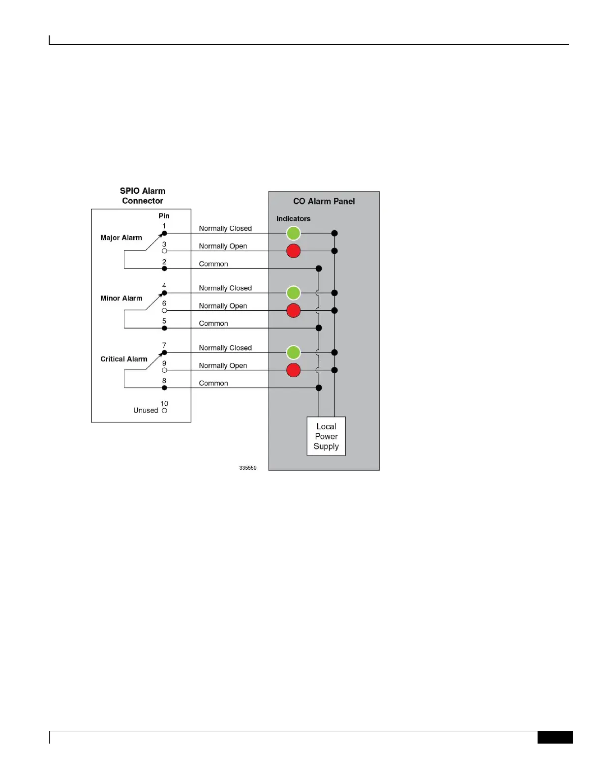
Central Office Alarm Wiring Example
The following figure depicts how the dry-contact relays can each control up to two external alarm indicators. In this
example, the CO alarm interface is connected to a CO Alarm Panel, where green LEDs are wired to indicate normal
operation, and red LEDs are wired to indicate an alarm condition.
Figure 65. CO Alarm Interface Schematic
With all relays de-energized (normally closed), the green LED is illuminated. If an alarm relay is energized, the NO
(normally open) contact closes and the red LED is illuminated.

 Loading...


