ASR 5000 Installation Guide ▄
Step a Unsnap the plastic bezel from the lower-front of the chassis by placing your fingers in the notches
on the sides of the bezel and pulling it toward you. Place it to the side for re-installation later.
Step b Use a Phillips #1 screwdriver to loosen the four captive screws that hold the fan tray cover/EMI
shield in place. Pull the cover away from the chassis. Do NOT use an electric or pneumatic torque
driver to loosen these screws.
Step c Pull the fan tray toward you using the handle. The fan tray should easily slide out of the chassis.
Place it to the side for re-installation later.
WARNING: To avoid personal injury and/or damage to the fan tray, be sure to support the fan tray’s weight from
its front and back as you slide it completely out of the chassis. Vorsicht beim Herausziehen der Luefter-Schublade: um
eine Beschaedigung des Moduls und eventuelle Verletzungen zu vermeiden, sollte diese hinten und vorne unterstuetzt
werden.
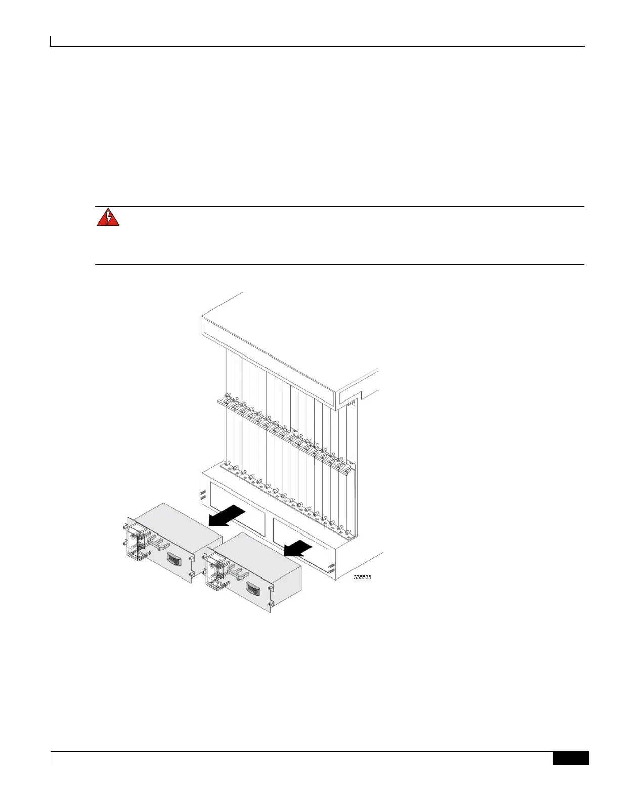
Step 3 Remove the PFUs located in the lower-rear of the chassis.
Step a Locate the PFU bay labeled Power Filter Unit 1 on the lower-left rear of the chassis.
Step b Use a Phillips #2 screwdriver to loosen the four screws that secure the PFU in to the chassis.
Step c Grasp the handle on the PFU and gently pull the PFU toward you. The PFU should slide easily out
of the chassis. Place it to the side for re-installation later.

 Loading...


