ASR 5000 Installation Guide ▄
Step d Replace the fan tray bay cover/EMI shield. The perpendicular tabs on the cover should face away
from the chassis and be positioned at the bottom. Use a Phillips #1 screwdriver to hand tighten the four
captive screws in an alternating pattern – upper left, lower right, lower left, upper right (5 inch-lb,
0.5 N-m). Do NOT use an electric or pneumatic torque driver to tighten these screws.
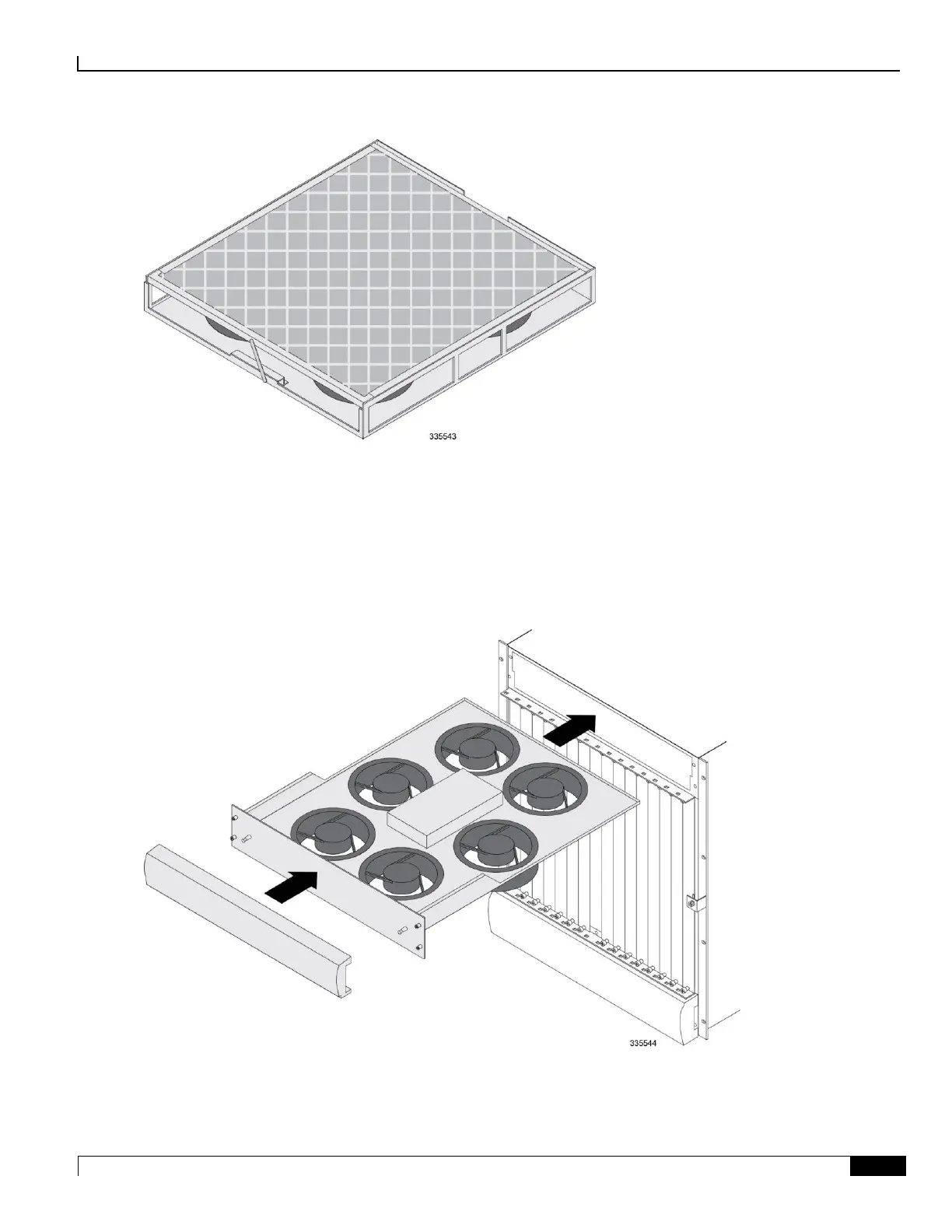
Step e Replace the lower plastic bezel: align it over the bezel mounts that protrude from the fan tray bay
cover and snap it in place.
Step 3 Re-install the upper fan tray.
Step a Hold the front of the fan tray by its sides and align it with the upper fan tray bay of the chassis. The
upper fan tray bay is located at the upper-front of the chassis.

 Loading...


