5-3
Cisco CRS-1 Series Carrier Routing System Getting Started Guide
Chapter 5 Initial Configuration of the Cisco IOS XR Software
Configuring the Management Ethernet Interface
Table 5-2 provides examples of Management Ethernet interface instances for a single-chassis system.
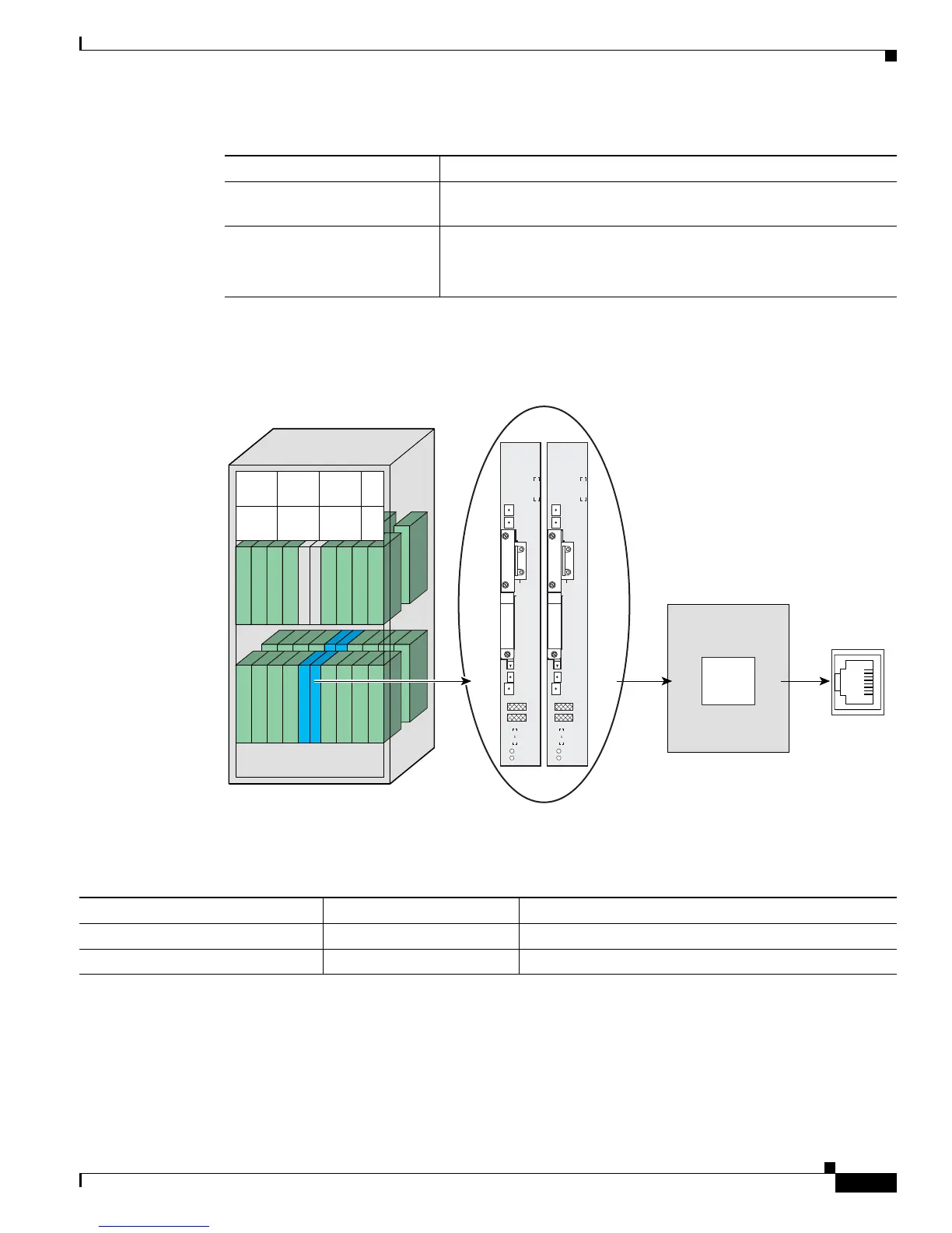
Figure 5-1 illustrates the syntax for the Management Ethernet interface instance.
Figure 5-1 Location for the Route Processor Management Ethernet Port
Table 5-2 Management Interface Instance for a Single-Chassis System
Displaying the Available Management Ethernet Instance
To display the Management Ethernet interface instances on the primary RP, enter the interface
MgmtEth ? command in global configuration mode:
RP/0/RP0/CPU0:router# configure
slot Physical slot of the card where the interface is located. For RPs, the
slot is “RP0” or “RP1.”
module The module is “CPU0.”
Note A module is an entity on a card that executes user commands
or communicates with a port (interface).
Table 5-1 Instance Syntax Description
Syntax Components Description
PLIM
PL8
PLIM
PL9
PLIM
PL
10
PLIM
PL
11
PLIM
PL
12
PLIM
PL
13
PLIM
PL
14
PLIM
PL
15
Line cardLine card
PLIM
PL0
PLIM
PL1
PLIM
PL2
PLIM
PL3
PLIM
PL4
PLIM
PL5
PLIM
PL6
PLIM
PL7
FC0
FC1
A0
B0
A1
B1
A2
B2
AM0
AM1
RP0
RP1
CPU0
Type and Rack=MgmntEth0 Slot=RP0 or RP1 Module=CPU0 Port=0
RP Card
116540
Console
AUX
PC Card
(disk1:)
MGMT ETH
CNTL ETH 1
CNTL ETH 0
Primary
Status
HDD
RP
Console
AUX
PC Card
(disk1:)
MGMT ETH
CNTL ETH 1
CNTL ETH 0
Primary
Status
HDD
RP
Management Interface Instance Syntax Example
Route processor in slot RP0 MgmtEth0/RP0/CPU0/0 router(config)# interface MgmtEth0/RP0/CPU0/0
Route processor in slot RP1 MgmtEth0/RP1/CPU0/0 router(config)# interface MgmtEth0/RP1/CPU0/0
 Loading...


