1-7
Cisco CRS-1 Series Carrier Routing System Getting Started Guide
Chapter 1 Getting Started on the Cisco CRS-1 Router
Hardware Overview: Single-Chassis System
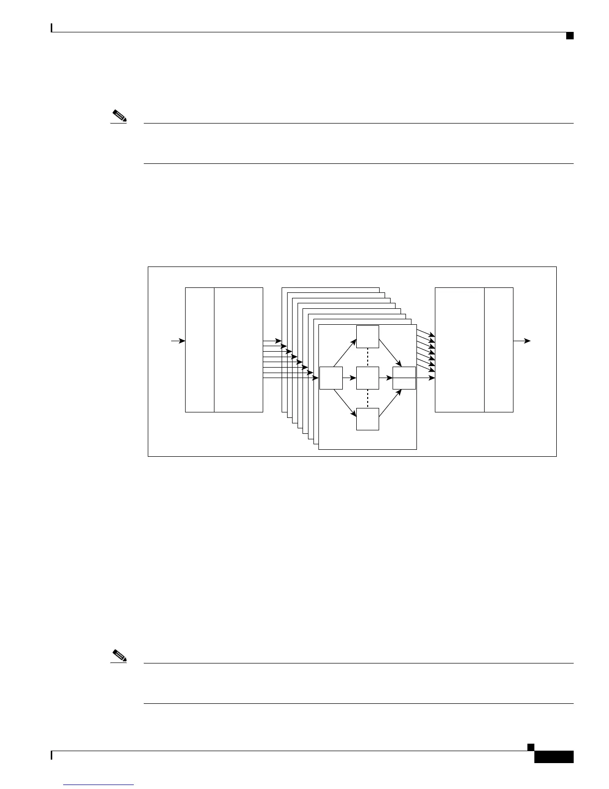
In a single-chassis system, all three stages of the switch fabric are contained in the switch fabric modules
(Figure 1-5).
Note The switch fabric cards are different for the Cisco CRS-1 16-Slot Line Card Chassis and the Cisco
CRS-1 8-Slot Line Card Chassis. For more information, refer to the hardware documentation listed in
the “Related Documents” section on page xii.
The switch fabric is partitioned into eight planes, and each MSC normally sends and receives traffic from
all planes simultaneously. This modular fabric architecture provides redundancy and fault tolerance. The
system can withstand the loss of a single plane without performance degradation. Loss of multiple planes
of the switch fabric results in degraded performance but does not cause the system to fail.
Figure 1-5 Switch Fabric in Single-Chassis System
Route Processors
The RPs provide central administrative and software control, including operation of the Cisco IOS XR
operating system, configuration and file storage, user interface connectivity, and system control.
Two RP cards are required per chassis for redundancy, and are installed in slots RP0 and RP1 of the line
card chassis. One RP controls the system as the primary RP. The second standby RP is a redundant card
that contains a complete backup of the system software and configuration. If the primary RP fails or goes
off line, the standby RP automatically assumes the role of primary RP. The arbitration between primary
and standby RPs occurs automatically on system startup. The primary RP can be identified by the green
Primary LED on the faceplate of the card, or by entering the show redundancy command.
Figure 1-6 illustrates the connections, storage devices, and status lights on the RP module for the Cisco
CRS-1 8-Slot Line Card Chassis.
Note The Cisco CRS-1 16-Slot Line Card Chassis and the Cisco CRS-1 8-Slot Line Card Chassis use different
RPs. To see the RP faceplate illustration for the Cisco CRS-1 16-Slot Line Card Chassis, see the
“Connecting and Communicating with the Router” section on page 2-1.
IP
Data
IP
Data
93761
PLIM MSC
Ingress
PLIMMSC
Egress
Line card chassis
S2
S3
S3
S2S1
S2
1 of 8
 Loading...


