1-8
Cisco CRS-1 Series Carrier Routing System Getting Started Guide
Chapter 1 Getting Started on the Cisco CRS-1 Router
Hardware Overview: Single-Chassis System
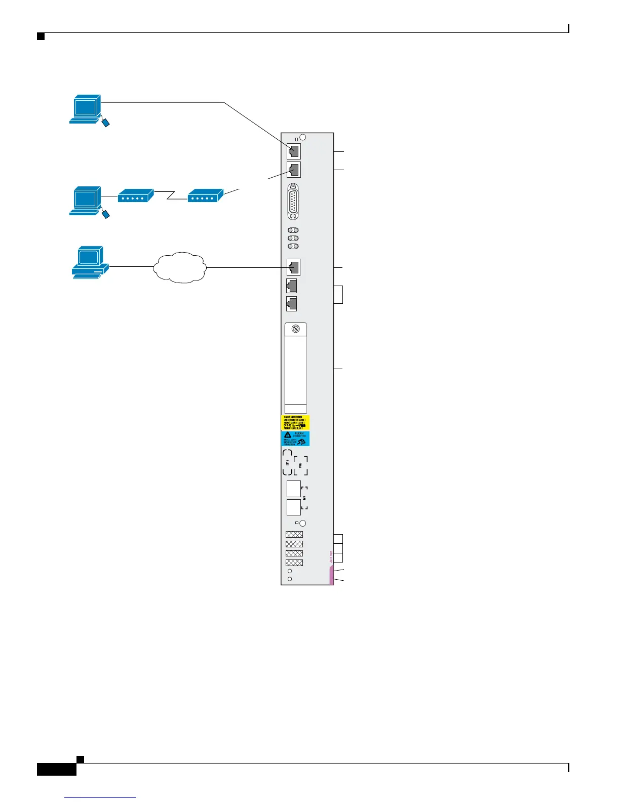
Figure 1-6 RP Faceplate for the Cisco CRS-1 8-Slot Line Card Chassis
Each RP contains:
• A Management Ethernet port for 10/100/1000 Ethernet connectivity to the user network. See the
“Configuring the Management Ethernet Interface” section on page 5-2 for more information.
• A hard disk used for storing user files, system logs, and temporary files.
Primary
Status
Console
AUX
CRITICAL
MAJOR
MINOR
122803
Optical GigE for control plane:
not user-configurable
Terminal connection
Modem connection
Primary RP (On=Primary)
Card status (Green=OK)
User-removable flash disk1:
stores installation PIE files.
A second internal Flash disk0:
stores installed software and
active configurations.
Management Ethernet connection
for out-of-band network communication
LED status
displays
(alphanumeric)
ALARM
PID/VID
MGMT
ETH
CNTL
ETH 0
PC
CARD
CNTL
ETH 1
EXT
CLK 1
EXT
CLK 2
Remote terminal for
CLI communication.
RJ-45 cable
Local terminal or
terminal server for
CLI communication.
RJ-45 cable
Remote CLI, CWI, XML,
or SNMP communication.
Remote file storage.
Ethernet cable
Network
 Loading...


