GR740-UM-DS, Nov 2017, Version 1.7 286 www.cobham.com/gaisler
GR740
19 Fault-tolerant 8/16-bit PROM/IO Memory Interface
19.1 Overview
The combined 8/16-bit memory controller provides a bridge between external memory and the AHB
bus. The memory controller can handle two types of devices: PROM and memory mapped I/O
devices (IO). The PROM area can be EDAC-protected using a (39,7) BCH code. The BCH code pro-
vides single-error correction and double-error detection for each 32-bit memory word.
The memory controller is configured through three configuration registers accessible via an APB bus
interface. The external data bus can be configured in 8-, 16-bit mode, depending on application
requirements. The controller decodes two address spaces on the AHB bus (PROM, IO)
External chip-selects are provided for up to two PROM banks and one IO bank. Figure 22 below
shows how the connection to the different device types is made.
19.2 PROM access
Up to two PROM chip-select signals are provided for the PROM area, PROM_CEN[1:0]. The size of
the banks can be set in binary steps from 16 KiB to 256 MiB.
A read access to PROM consists of two data cycles and between 0 and 240 waitstates. The read data
(and optional EDAC check-bits) are latched on the rising edge of the clock on the last data cycle. On
non-consecutive accesses, a idle cycle is placed between the read cycles to prevent bus contention due
to slow turn-off time of PROM devices. Figure 23 shows the basic read cycle waveform (zero wait-
state) for non-consecutive PROM reads. Note that the address is undefined in the idle cycle. Figure 24
shows the timing for consecutive cycles (zero waitstate). Waitstates are added by extending the data2
phase. This is shown in figure 25 and applies to both consecutive and non-consecutive cycles. Only an
even number of waitstates can be assigned to the PROM area.
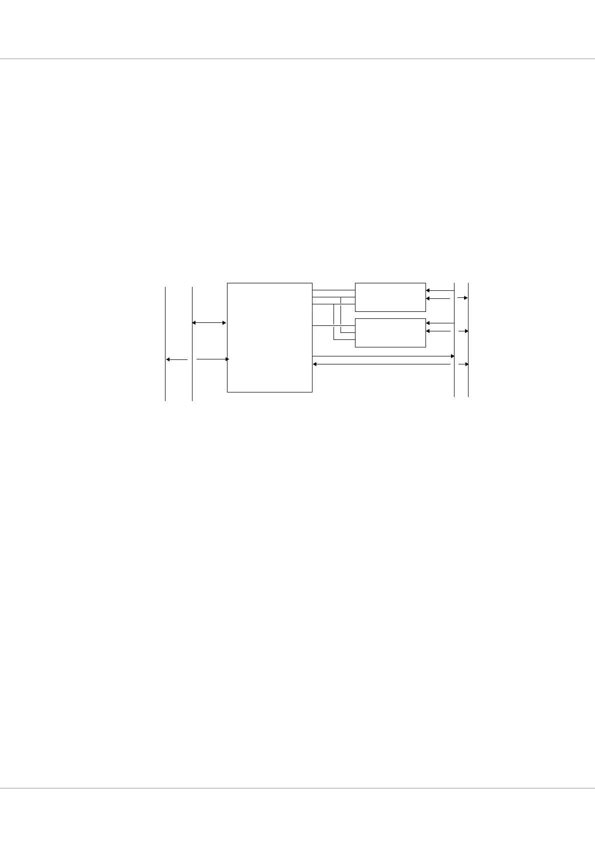
Figure 22. FTMCTRL connected to different types of memory devices
CS
OE
WE
A
D
PROM
CS
OE
WE
I/O
PROM_CEN[1 :0]
PROMIO_OEN
PROMIO_WEN
IO_SN
AD
FTMCTRL
PROMIO_ADDR[27:0]
PROMIO_DATA[15:0]
AHBAPB
APB
AHB
A
D