GR740-UM-DS, Nov 2017, Version 1.7 263 www.cobham.com/gaisler
GR740
17 CAN 2.0 Controllers with DMA
17.1 Overview
The CAN controller supports transmission and reception of sets of messages by use of circular buffers
located in memory external to the core. Separate transmit and receive buffers are assumed. Reception
and transmission of sets of messages can be ongoing simultaneously. This device has two CAN con-
trollers, connected to the same two CAN busses.
After a set of message transfers has been set up via the AMBA APB interface the DMA controller ini-
tiates a burst of read accesses on the AMBA AHB bus to fetch messages from memory, which are per-
formed by the AHB master. The messages are then transmitted by the CAN core. When a
programmable number of messages have been transmitted, the DMA controller issues an interrupt.
After the reception has been set up via the AMBA APB interface, messages are received by the CAN
core. To store messages to memory, the DMA controller initiates a burst of write accesses on the
AMBA AHB bus, which are performed by the AHB master. When a programmable number of mes-
sages have been received, the DMA controller issues an interrupt.
The CAN controller can detect a SYNC message and generate an interrupt. The SYNC message iden-
tifier is programmable via the AMBA APB interface. Separate synchronisation message interrupts are
provided.
The CAN controller can transmit and receive messages on either of two CAN busses, but only on one
at a time. The selection is programmable via the AMBA APB interface.
Note that it is not possible for the same controller to receive a CAN message while transmitting one.
The controller implements the following functions:
• CAN protocol
• Message transmission, filtering and reception
• SYNC message reception
• Status and monitoring
• Interrupt generation
• Redundancy selection
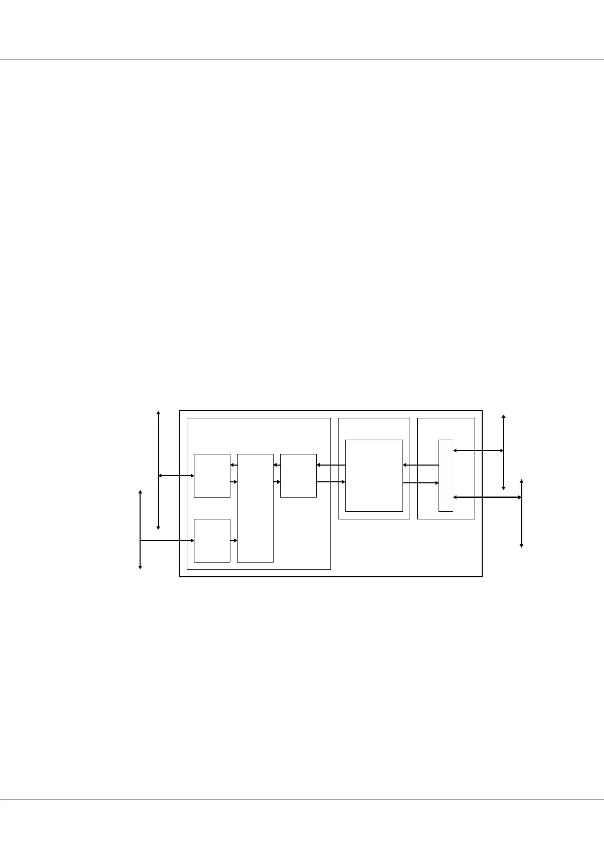
Figure 21. Block diagram of one CAN controller
GRCAN
DMA
AMBA
APB
Slave
AMBA Layer
Mux / DeMux
Coding Layer
FIFO
AMBA
AHB
Master
APB
Nominal CAN bus
Master IO bus
Physical Layer
Redundant CAN bus
CAN 2.0
Codec
Controller